a led light

A technology for LED lamps and lamp posts, applied in the field of lighting, can solve the problems of inability to plug and use normally, loose plug connection of power supply sockets, weak setting of power supply pins, etc., to achieve the effect of automatic power supply connection and prevention of detachment or loosening.

Inactive Publication Date: 2018-03-23
中山市中千智享电器科技有限公司
View PDF5 Cites 0 Cited by
  • Summary
  • Abstract
  • Description
  • Claims
  • Application Information

AI Technical Summary

Problems solved by technology

[0002] LED lamps have gradually replaced the existing incandescent lamps and fluorescent lamps as the new generation of lighting equipment used on stages such as wedding celebrations and evening parties. In order to achieve quick setup and use, most LED lamps are mostly set in one piece, and can be powered by plugging in when using , while the power supply line of the existing LED lights is very inconvenient to carry or place when it is not in use. The power supply pins on the device are too weak, and will be bent and damaged if people accidentally step on it or use too much force when plugging in, making it impossible to plug in normally and shorten the service life. meet existing needs

Method used


Image

  • a led light
  • a led light
  • a led light

Examples


Embodiment Construction

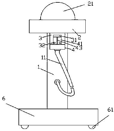
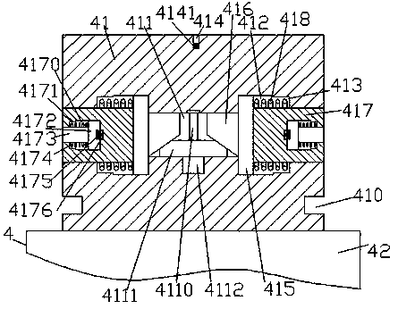
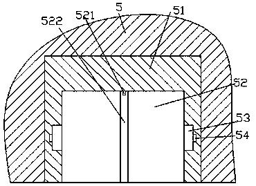
[0023] Such as Figure 1-Figure 7 As shown, an LED lamp of the present invention includes a socket 51 arranged in the power supply seat 5, a lamp post 1, a platform 2 fixed on the top of the lamp post 1, and a clamping member arranged at the bottom of the platform 2 3. The plug-in head 4 engaged in the clamping member 3 and the base 6 fixedly connected to the bottom of the lamp column 1, the top surface of the platform 2 is provided with an LED lamp 21, and the bottom surface of the base 6 is provided with a peripheral There are multiple sets of rollers 61, so as to facilitate the movement of the device. The plug head 4 includes a fastening part 41 and a force application part 42 fixed on the bottom of the fastening part 41. The top end surface of the fastening part 41 is provided with There is a hole 414, a sensor 4141 is arranged in the hole 414, a first sliding cavity 411 is arranged in the insertion part 41 below the hole 414, and the left and right sides of the first slid...


PUM


Abstract

The invention discloses an LED lamp. The LED lamp comprises an insertion sleeve arranged in a power supply base, a lamp column, a platform fixed at the top of the lamp column, a clamping piece arranged at the bottom of the platform, a plug clamped in the clamping piece, and a base fixedly connected with the bottom of the lamp column; the LED lamp is arranged on the top end surface of the platform; multiple sets of rollers are peripherally arranged on the bottom end surface of the base; the plug includes an insertion part, and a force applying part fixed at the bottom of the insertion part; a hole groove is formed in the top end surface of the insertion part; a sensor is arranged in the hole groove; a first slip cavity is formed in the insertion part below the hole groove; second slip cavities are uniformly arranged on the left and right sides of the first slip cavity; first cavities are formed in one sides, leaving from the first slip cavity, of the second slip cavities; first slip blocks are arranged in the second slip cavities; inclined angle blocks for entering the first slip cavity are arranged on the inner sides of the first slip blocks; locking blocks for penetrating through the first cavities and the outer side wall body of the insertion part are arranged on the outer sides of the first slip blocks; a screw rod is arranged in the first slip cavity; and the bottom of the screw rod is connected with a motor. The LED lamp is simple in structure, convenient to use, automatic in control, convenient to insert and high in stability after insertion, prevents interrupted power supply due to accidental touch, and meanwhile, prolongs the service life.

Description

technical field [0001] The invention relates to the technical field of lighting, in particular to an LED lamp. Background technique [0002] LED lamps have gradually replaced the existing incandescent lamps and fluorescent lamps as the new generation of lighting equipment used on stages such as wedding celebrations and evening parties. In order to achieve quick setup and use, most LED lamps are mostly set in one piece, and can be powered by plugging in when using , while the power supply line of the existing LED lights is very inconvenient to carry or place when it is not in use. The power supply pins on the device are too weak, and will be bent and damaged if people accidentally step on it or use too much force when plugging in, making it impossible to plug in normally and shorten the service life. meet existing needs. Contents of the invention [0003] The technical problem to be solved by the present invention is to provide an LED lamp, which can solve the above-menti...

Claims


Application Information

Patent Timeline
Patent Type & Authority Patents(China)
IPC IPC(8): F21S6/00F21V17/16F21V23/06F21Y115/10
CPCF21S6/005F21V17/164F21V23/06
Inventor 张巧巧
Owner 中山市中千智享电器科技有限公司
Why Eureka
Try Eureka