Prone positioning therapeutic bed

a technology of prone positioning and therapeutic beds, which is applied in the field of therapeutic beds, can solve the problems of obstructing the access to the head of the patient, obstructing the access to the patient in the supine position, and obstructing the access to the patien

Inactive Publication Date: 2004-01-06
HUNTLEIGH TECH LTD
View PDF21 Cites 93 Cited by
  • Summary
  • Abstract
  • Description
  • Claims
  • Application Information

AI Technical Summary

Benefits of technology

The present bed further includes a lock pin mounted to the base frame that is insertable into a cooperating hole of a locking ring on the patient support platform to mechanically prevent rotation of the patient support platform. Preferably, the lock pin assembly incorporates a detent and a pair of proximity switches that indicate the position of the lock pin with respect to the locking ring and electrically control whether the patient support platform is allowed to rotate. The lock pin may be twistable to engage a protrusion on the lock pin with the patient support platform and thereby prevent retraction of the pin from its locked position.
It is an object of the present invention to provide a therapeutic bed having a split end ring at the head of the bed for improved access to the head of a patient lying on the bed and for placement or removal of the patient from the bed without disconnecting patient care lines from the patient.
It is a further object of the present invention to provide a therapeutic bed having side rails that fold underneath the patient support platform of the bed for improved bedside access to the patient.
Another object of this invention is to provide a prone positioning therapeutic bed having a locking pin for mechanically preventing rotation of the patient support platform as desired.
Still another object of this invention is to provide a prone positioning therapeutic bed having a locking pin with cooperating proximity switches for electrically preventing rotation of the patient support platform as desired.
A further object of this invention is to provide a rotating therapeutic bed having a locking pin that is twistable to prevent disengagement of the locking pin.

Problems solved by technology

One drawback of such an arrangement is that the continuous end ring obstructs access to the head of the patient.
Additionally, the initial placement of a patient on the bed requires disconnection of all patient care lines, and to remove a patient care line from the end ring requires that one end of the patient care line be unplugged from either the patient or the piece of equipment to which the line is attached, which can be very inconvenient and may jeopardize the patient, depending on the particular condition of the patient.
Although the patient support packs may be flipped to the outside of the bed to uncover the patient in the supine position, the side rails remain upright and thus obstruct access to the patient in the supine position.
One of the problems in the art of prone positioning therapeutic beds is to provide electrical connections to the bed for both the power and controller equipment that moves the bed and for the patient monitoring systems on the bed.
However, due to vibration and other abrupt movements, such wire brushes cause problems of electrical intermittence, which can be detrimental to the therapy of the patient.
Another problem in the field of prone positioning beds is to sufficiently support the head of a patient during rotation.
However, such straps are generally uncomfortable for the patient and do not provide sufficient lateral support for the patient's head.
Additionally, such straps do not provide sufficient adjustability.
However, such drive systems generally prevent manual rotation of the patient support platform by medical personnel.
However, such lock pins may be jostled loose under the influence of vibration and other abrupt movements of the bed.
However, such a rotary opto encoder is fairly cumbersome and must be reinitialized by moving to an index location in the event of power interruptions.

Method used


Image

  • Prone positioning therapeutic bed
  • Prone positioning therapeutic bed
  • Prone positioning therapeutic bed

Examples


Embodiment Construction

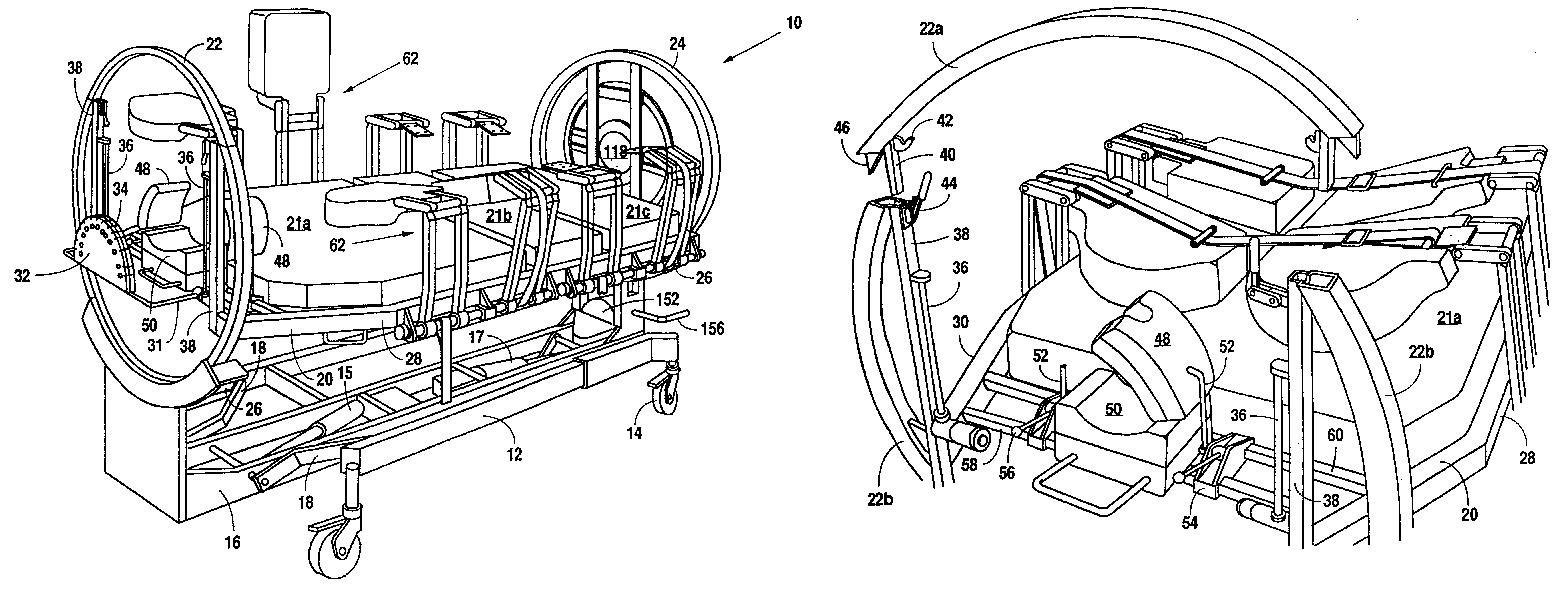
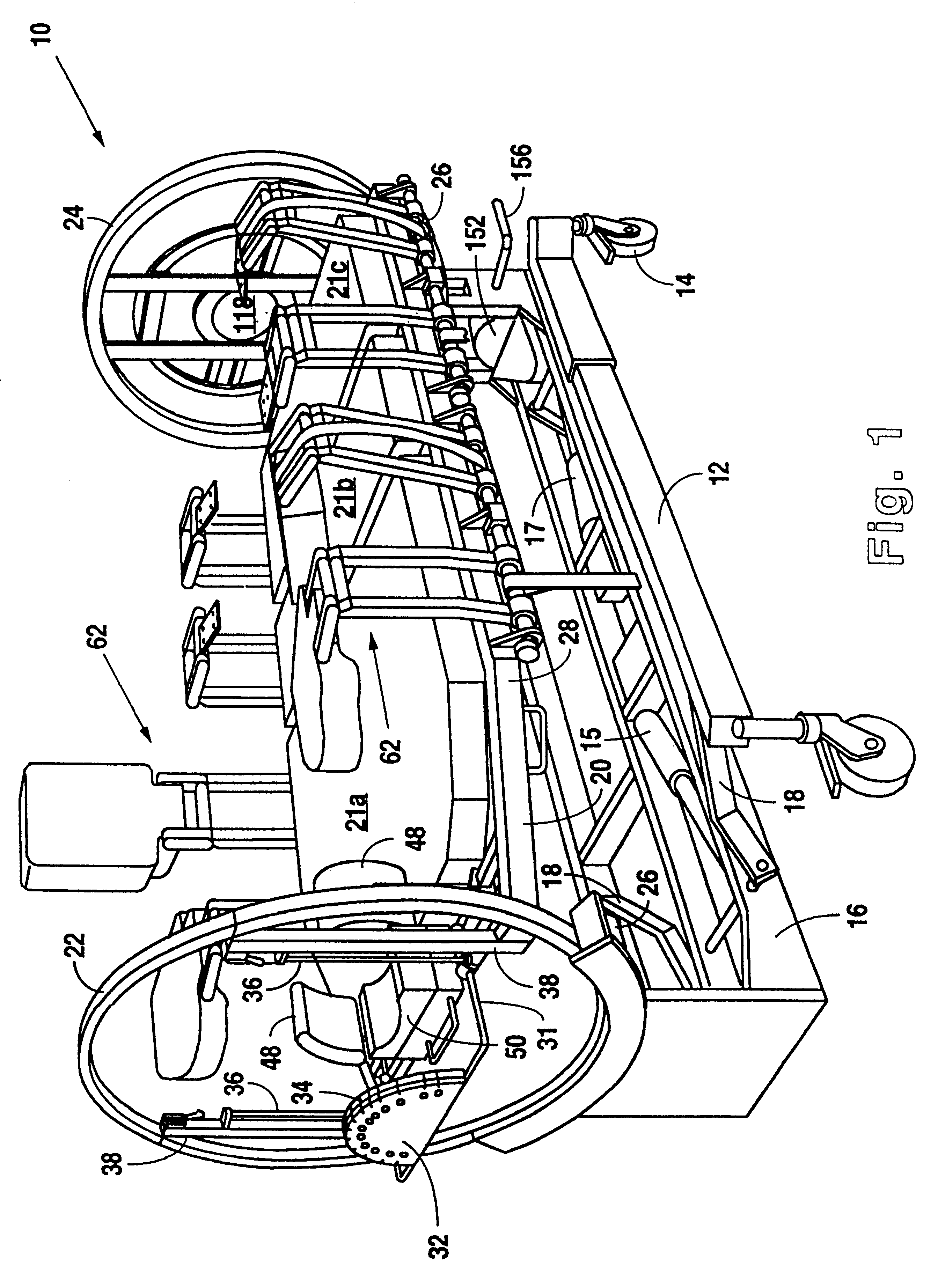
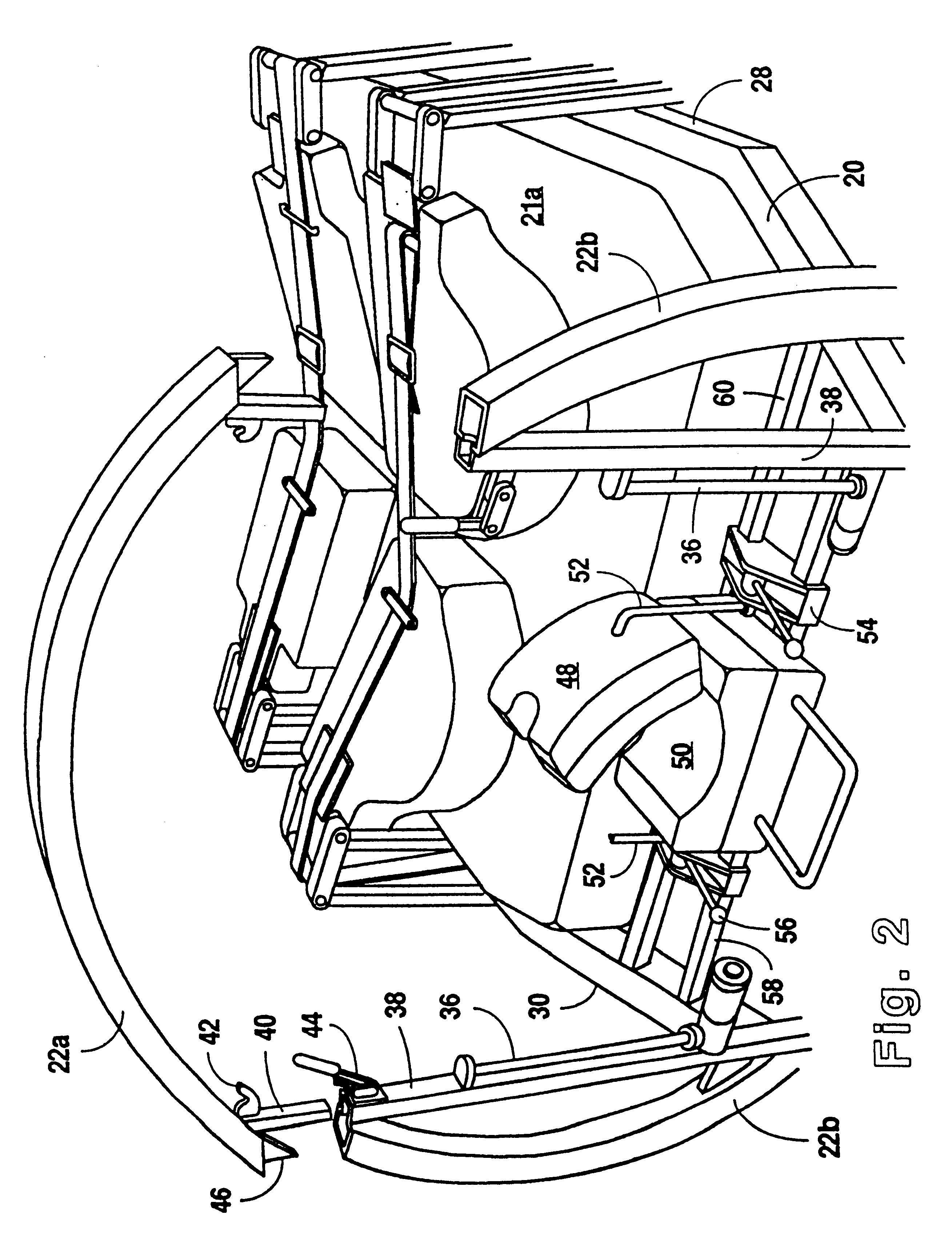
Referring to FIGS. 1 and 2, a therapeutic bed 10 in accordance with the present invention preferably comprises a ground engaging chassis 12 mounted on wheels 14. A base frame 16 is mounted on chassis 12 with pivot linkages 18. Rams 15, 17 housed within base frame 16 cooperate with pivot linkages 18 to form a lift system to raise and lower base frame 16 on chassis 12. A patient support platform 20 having upright end rings 22, 24 is rotatably mounted on base frame 16 with rollers 26 such that patient support platform 20 may rotate about a longitudinal axis between a supine position and a prone position. Side support bars 28, 30 extend between end rings 22, 24. At the head of bed 10, a guide body 32 having a plurality of slots 34 for routing patient care lines (not shown) is slidably mounted on rails 36 with support rod 31. Similarly, at the foot of bed 10, a central opening 118 is provided for receiving a removable patient care line holder (not shown) having a plurality of circumferen...


PUM


Abstract

A prone positioning therapeutic bed comprises a base frame, a patient support platform rotatably mounted on the base frame for rotational movement about a longitudinal rotational axis, a drive system for rotating the patient support platform on the base frame, and an upright end ring at the head of the bed with a central opening for routing patient care lines and a removable upper section for improved access to a patient's head. The patient support platform preferably has pivotally mounted side rails that fold underneath the patient support platform and straps with strap connectors that indicate whether the straps are sufficiently tensioned. A direct, wired electrical connection between the patient support platform and the base frame allows full rotation of the patient support platform in either direction. A manually operable lever disengages the patient support platform from the drive system to allow manual rotation of the patient support platform.

Description

1. Field of the InventionThis invention relates generally to therapeutic beds, and more particularly to an improved rotating bed capable of placing a patient in a prone position.2. Description of the Related ArtVarious types of therapeutic supports for bedridden patients have been well known for many years. For example, such therapeutic supports include but are not limited to low air loss beds, fluidized bead beds, and patient positioning beds. Patient positioning has been used in hospital beds for some time to enhance patient comfort, prevent skin breakdown, improve drainage of bodily fluids, and facilitate breathing. One of the goals of patient positioning has been maximization of ventilation to improve systematic oxygenation. Various studies have demonstrated the beneficial effects of body positioning and mobilization on impaired oxygen transport. The support of patients in a prone position can be advantageous in enhancing extension and ventilation of the dorsal aspect of the lun...

Claims


Application Information

Patent Timeline
Patent Type & Authority Patents(United States)
IPC IPC(8): A61G7/00A61G7/05
CPCA61G7/001A61G7/008A61G7/018A61G7/0507A61G2007/051A61G2007/0513A61G2007/0519A61G2007/0522A61G2007/0524A61G2007/0527A61G2203/34A61G2210/50A61G2203/42A61G7/051A61G7/0513A61G7/0519A61G7/0522A61G7/0524A61G7/0527
Inventor BARTLETT, ALAN L.KRYWICZANIN, WLADYSLAW H.NIEDERKROM, CHRISTOPHER T.
Owner HUNTLEIGH TECH LTD
Why Eureka
Try Eureka