Insertion tool for knotless suture anchor for soft tissue repair and method of use

a technology of soft tissue repair and insertion tool, which is applied in the field of medical devices and procedures, can solve the problems of pain and loss of function, high failure rate of surgical rotator cuff repair, and many of these techniques are relatively time-consuming

Active Publication Date: 2010-05-13
HOWMEDICA OSTEONICS CORP
View PDF102 Cites 229 Cited by
  • Summary
  • Abstract
  • Description
  • Claims
  • Application Information

AI Technical Summary

Benefits of technology

[0014]In one embodiment, the outer shaft has threads at its distal end which matingly engage threads on the inner wall of the outer tubular member. When the outer shaft is screwed into the outer tubular member, it will prevent the outer tubular member from rotating when suture thread is wrapped onto the rotating inner tubular member of the anchor.

Problems solved by technology

When the rotator cuff tears from the humerus, the result is pain and loss of function.
In this situation, it is less likely that the tendon will heal properly to the bone, resulting in a re-tear.
Many of these techniques can be relatively time-consuming when compared with open surgery.
There is a growing body of literature showing that surgical rotator cuff repair has a high rate of failure.
Failure of rotator cuff repairs is a well-described complication of rotator cuff repairs, both open and arthroscopic.
Tendon-to-bone reattachment in a rotator cuff repair procedure can fail by a number of means.
Stabile apposition between the tendon and bone will promote healing while micro-motion or oscillation between the tendon and the bone may disrupt the healing of the tendon to the bone.
Such a gap interferes with the healing of the tendon to the bone and may compromise the repair process to an extent that it becomes unsuccessful.
However, due to limitations in their design, current knotless anchors used for lateral fixation do not always adequately fix and tension the suture to the bone or are overly complicated to use, resulting in the potential for inadequate lateral fixation, possibly resulting in the formation of the gap shown in FIG. 2.
One problem with prior art knotless suture anchors is that the insertion tool used to fix the anchor into bone and to create tension on the sutures, are inadequate and too complex to securely implant the anchor and tension the suture.

Method used


Image

  • Insertion tool for knotless suture anchor for soft tissue repair and method of use
  • Insertion tool for knotless suture anchor for soft tissue repair and method of use
  • Insertion tool for knotless suture anchor for soft tissue repair and method of use

Examples


Embodiment Construction

[0073]FIGS. 24-30D relate to the insertion tool of the present invention, however, the tool can be used with numerous embodiments of a knotless suture anchor which are disclosed and described in FIGS. 3-23. Thus, a description of the various anchors in FIGS. 3-23 precedes the description of the insertion tool of the invention.

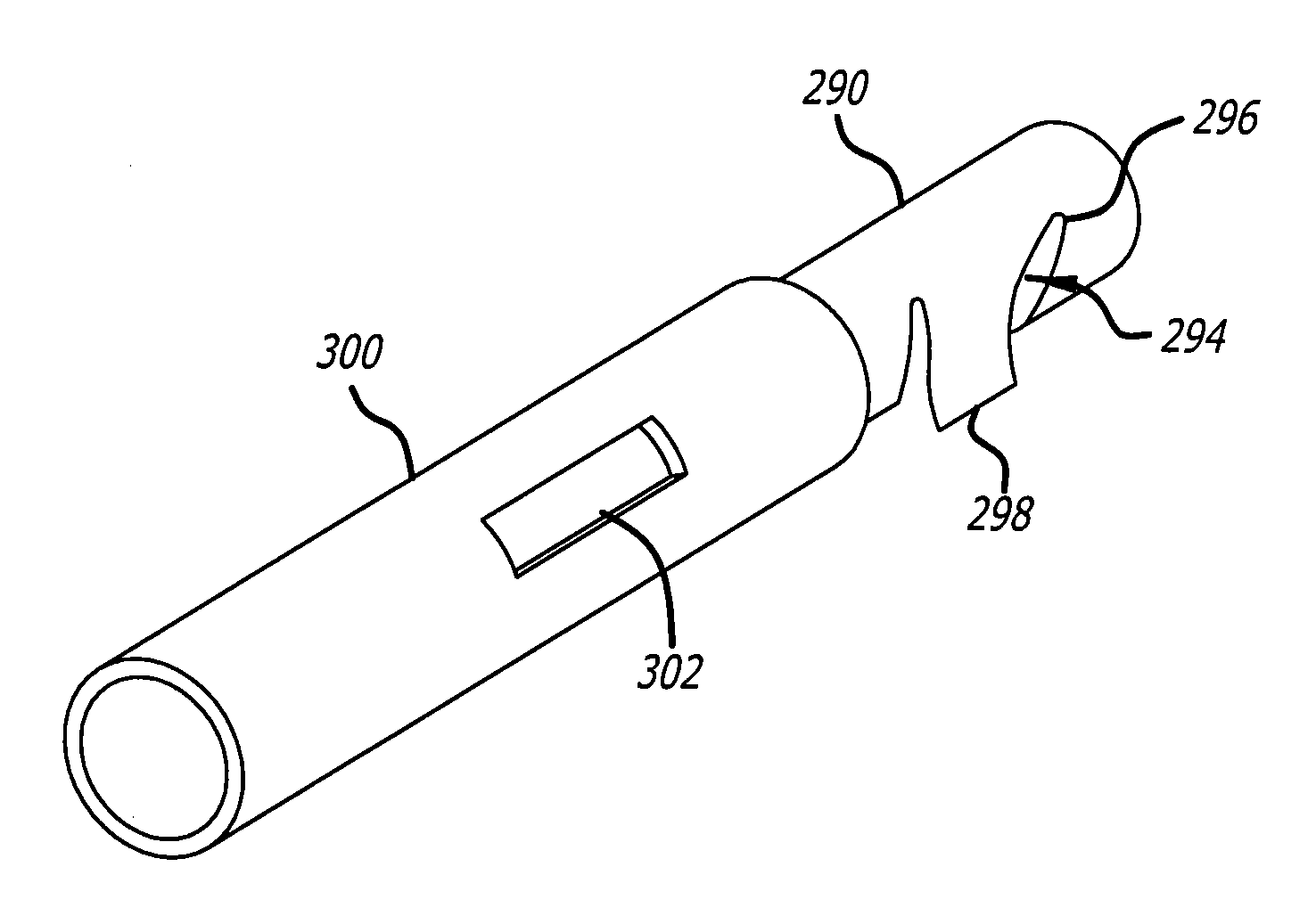
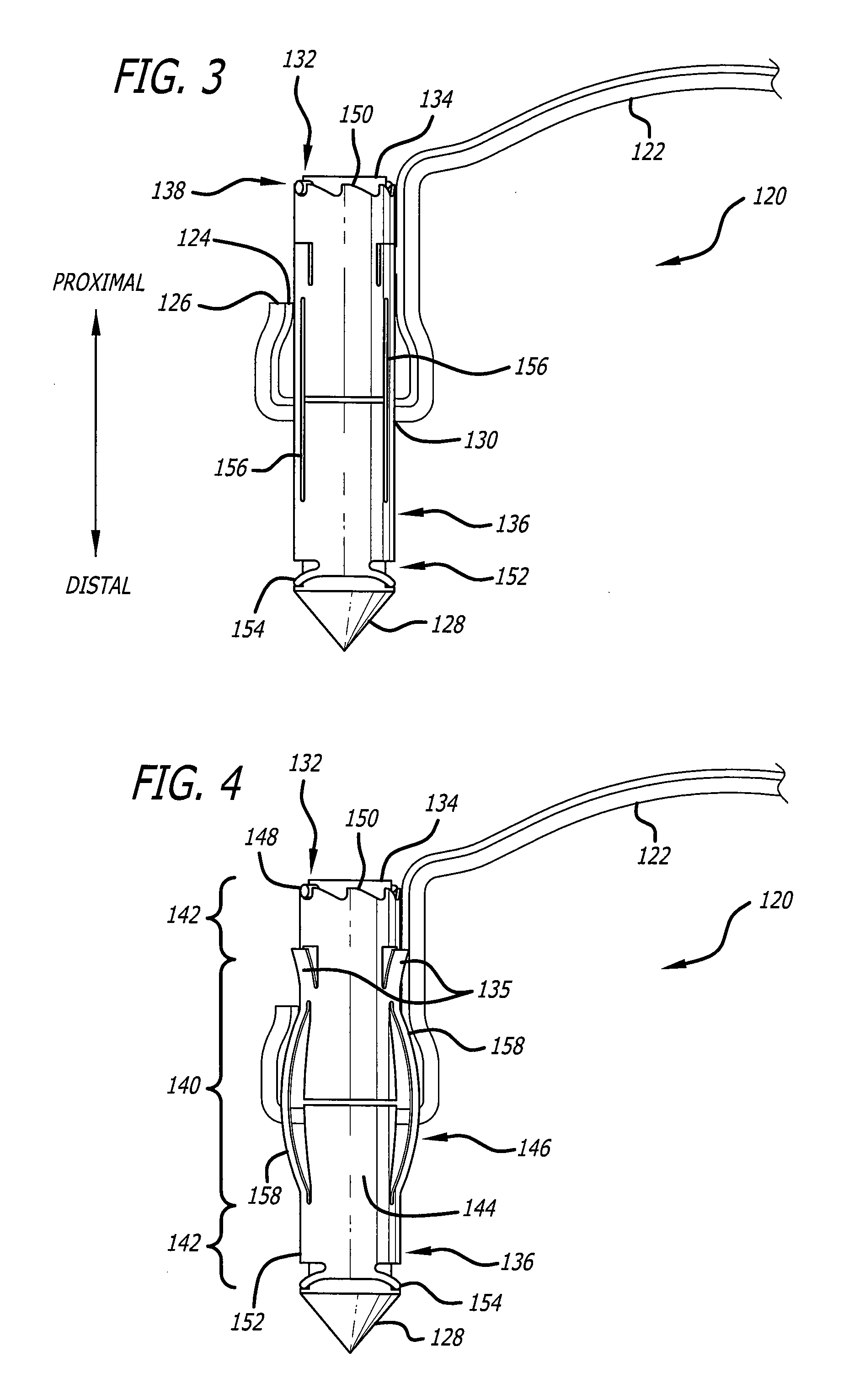
[0074]Referring now in more detail to the exemplary drawings for purposes of illustrating embodiments, wherein like reference numerals designate corresponding or like elements among the several views, FIG. 3 shows an assembled knotless suture anchor 120 in accordance with aspects of the invention. The anchor has received an unknotted suture thread 122 and the untied ends 124 and 126 of the thread are shown at the left of the anchor. The anchor has a pointed tip 128 for facilitating penetration of the anchor into the bone with impaction, an aperture 130 for receiving the suture, and a ratcheting mechanism 132 located at the proximal end 138 of the anchor, in thi...


PUM


Abstract

An insertion tool is used to implant a knotless suture anchor to secure soft tissue to a rigid structure such as bone. The anchor has an inner member that receives suture thread and rotates within an outer tubular member. An inner shaft on the insertion tool engages the inner tubular member and is used to rotate the inner tubular member so that the suture thread is wrapped onto the inner tubular member thereby increasing contact with the outer tubular member of the anchor which applies pressure to the wrapped suture thread to retain it in position on the inner tubular member while simultaneously and adjustably tensioning the suture thread. The insertion tool has an outer shaft that engages the outer tubular member of the anchor and prevents the outer tubular member from rotating as the inner shaft on the insertion tool rotates the inner tubular member on the anchor.

Description

FIELD OF THE INVENTION[0001]The present invention relates to medical devices and procedures, and more particularly, to methods and devices for approximation of soft tissue to a rigid material such as bone.BACKGROUND OF THE INVENTION[0002]There are many medical procedures where a surgeon needs to attach soft tissue to bone. The soft tissue can be tendon or other connective tissue. One very common example of this is rotator cuff repair where a portion or all of the rotator cuff is torn or detached from the humerus. When the rotator cuff tears from the humerus, the result is pain and loss of function. Rotator cuff disease affects a large number of people worldwide, affecting many people over the age of forty. Some studies have shown a prevalence of approximately 30% in people over the age of forty (Rockwood C., et al., The Shoulder, Saunders, 2004; 820-821). It is estimated that as many as 17 million people in the United States may be at risk for pain and dysfunction as a result of rot...

Claims


Application Information

Patent Timeline
Patent Type & Authority Applications(United States)
IPC IPC(8): A61B17/10A61B17/04A61B19/00
CPCA61B17/0401A61B17/888A61B17/8888A61B2017/00986A61B2017/0404A61F2002/0888A61B2017/0414A61B2017/045A61B2017/0451A61F2002/0858A61B2017/0409
Inventor VAN DER BURG, ERIKCOHEN, NATHANIELFEEZOR, CHRISTOPHERCHENG, CHRISTOPHER T.
Owner HOWMEDICA OSTEONICS CORP
Why Eureka
Try Eureka