This helps you quickly interpret patents by identifying the three key elements:
Problems solved by technology
Method used
Benefits of technology
[0010] In accordance with one embodiment of the invention, a device for grasping an implant is provided. The implant has a first and second surface, with at least one of the first and seconds surfaces being non-planar. The device includes a first grasping element having a first grasping surface that substantially conforms to the first surface of the implant, and a second grasping element having a second grasping surface substantially conforming to the second surface of the implant. At least one of t
Problems solved by technology
However, implants grasped by conventional metal implant graspers run the risk of being damaged.
Compounding this problem is that various implants have non-planar concave or convex surfaces that do not conform with the grasping surfa
Method used
Image
Click on the blue label to locate the original text in one second.
Reading with bidirectional positioning of images and text.
Examples
Example
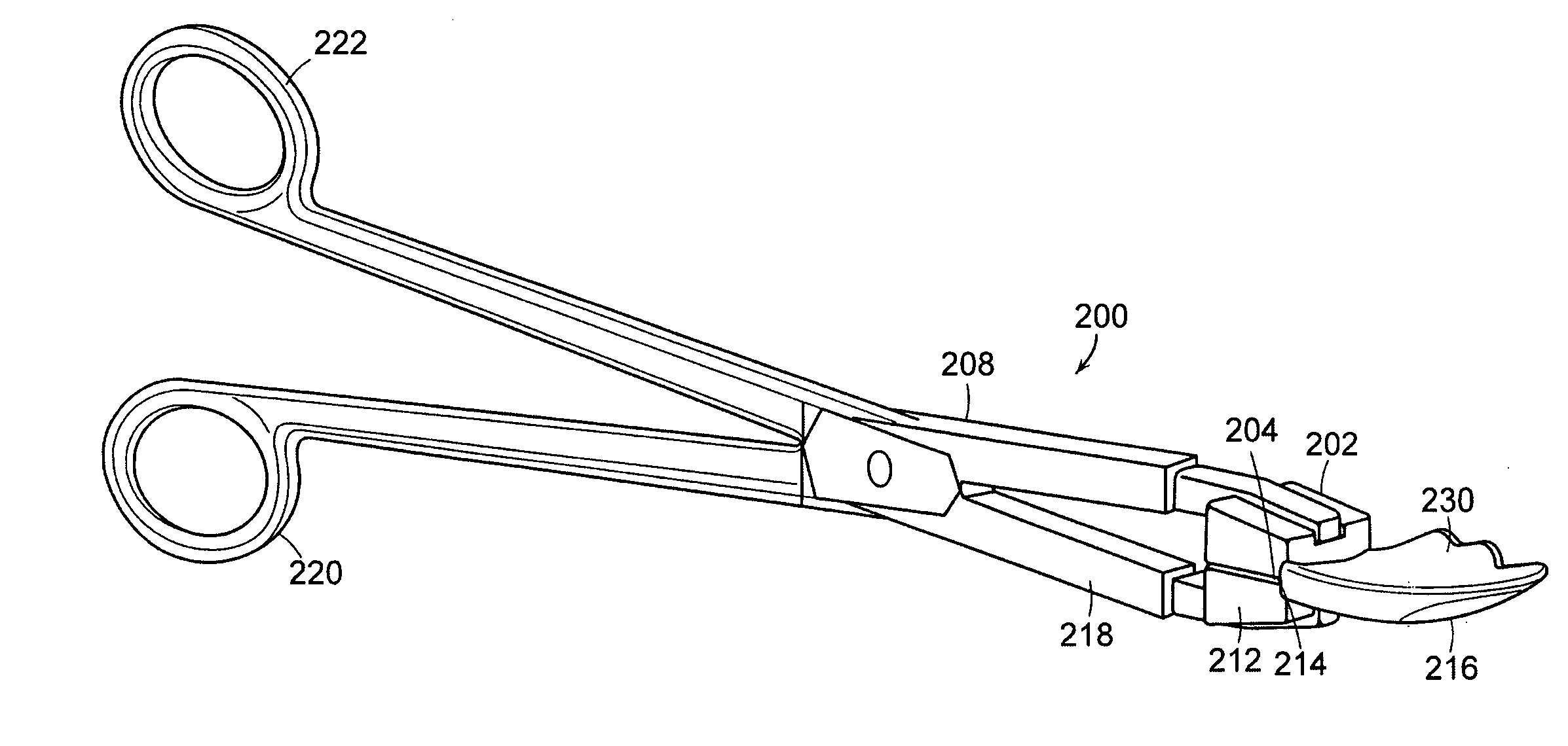
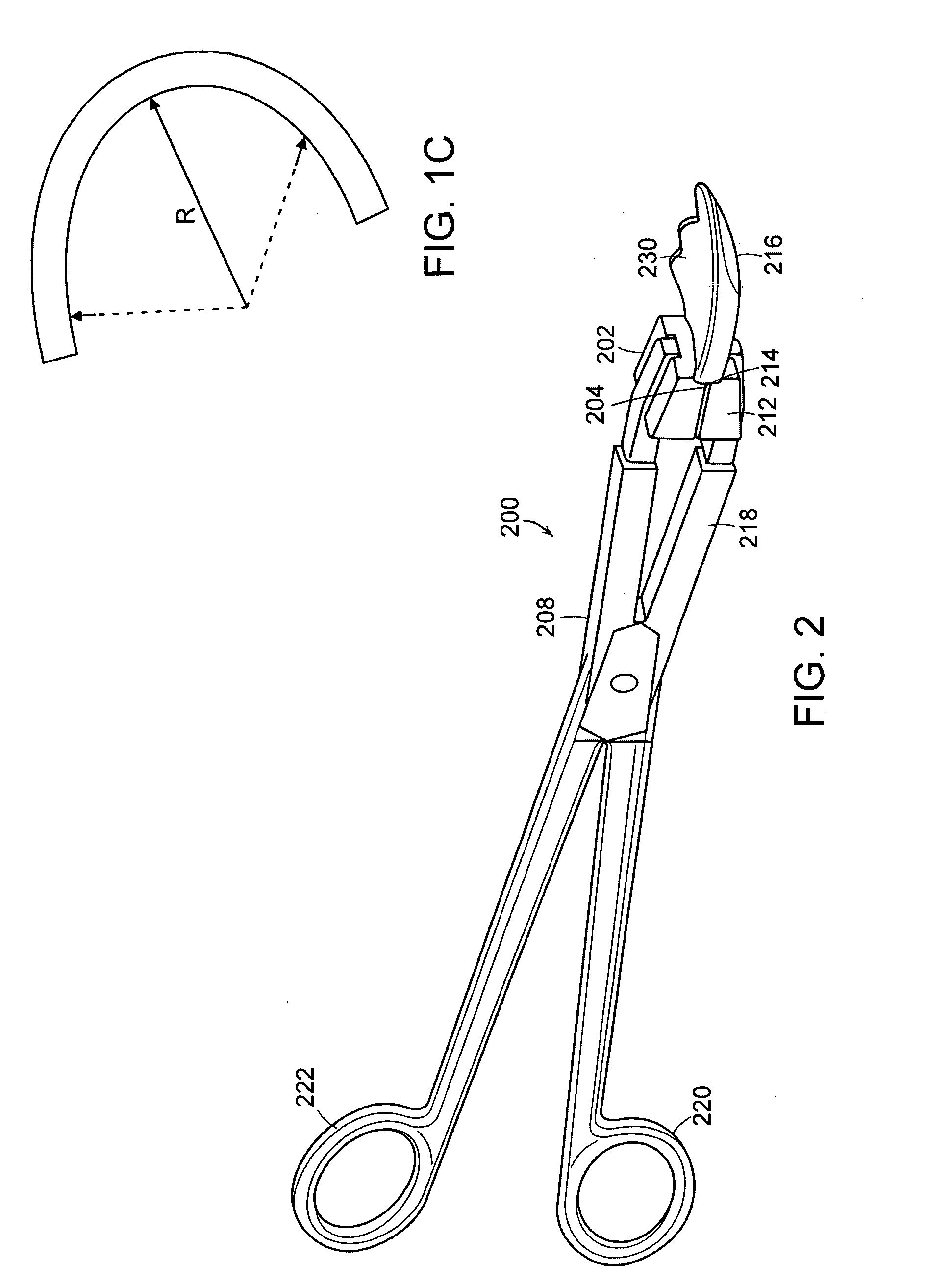
[0038] In illustrative embodiments, devices and methods for grasping an implant are presented that reduce the risk of scratching or otherwise damaging the implant. Various embodiments prevent rotation and slippage of the implant when being grasped. Details are discussed below.
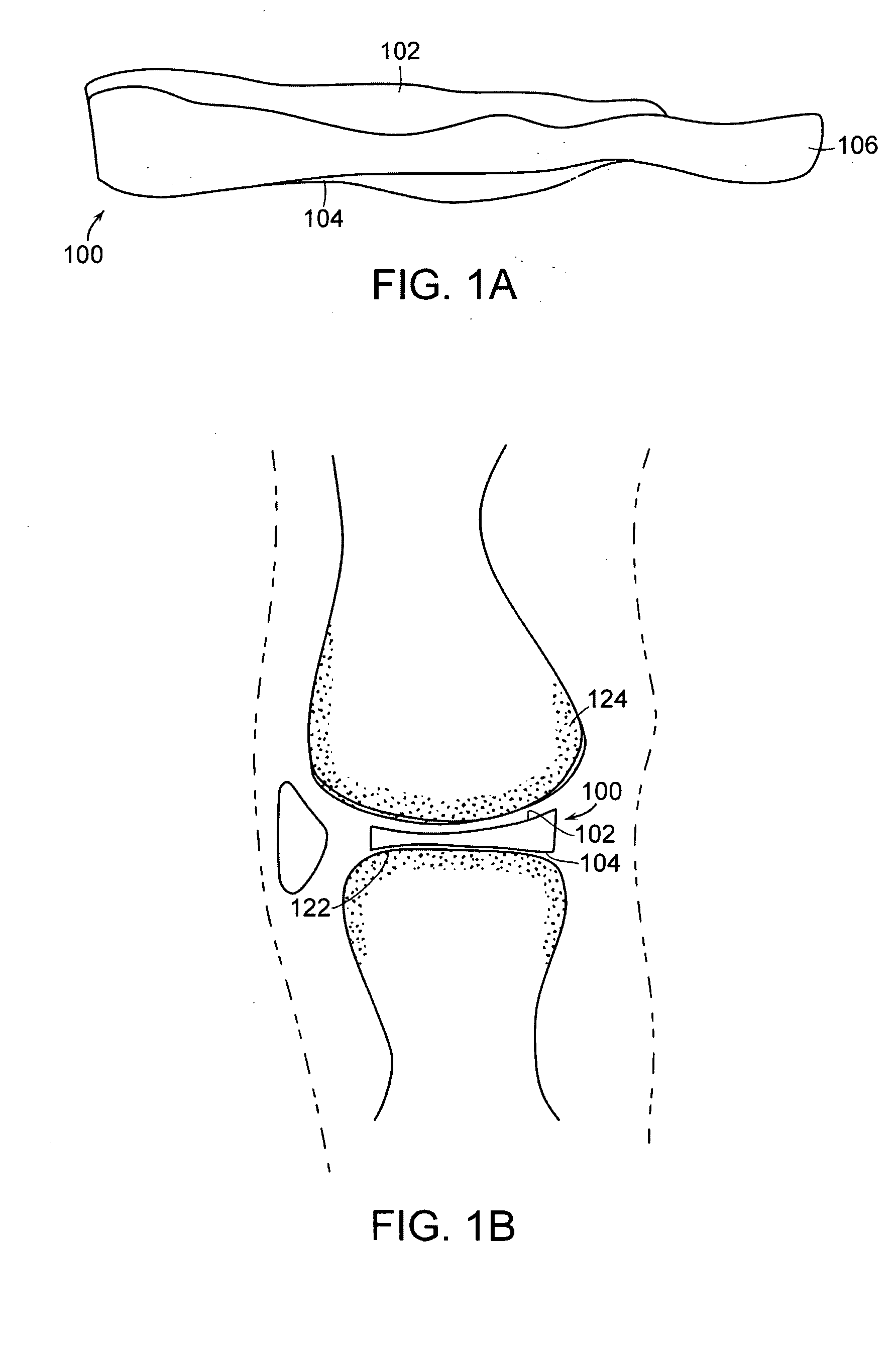
[0039]FIG. 1(a) is a slightly perspective top view of an exemplary implant 100 that may be grasped by a device, such as a surgical instrument, during an orthopedic procedure. The implant 100 is an interpositional knee implant, suitable for implantation at the tibial plateau of the knee joint, as described in U.S. patent application Ser. No. 10 / 997,407 entitled “Patient Selectable Knee Joint Arthroplasty Devices, filed Nov. 24, 2004, which is incorporated herein, it its entirety, by reference.
[0040] The implant 100 has an upper surface 102, a lower surface 104 and a peripheral edge 106. The upper surface 102 forms a mating surface for receiving the opposing joint surface (i.e., the upper surface 102 may substa...
PUM
Abstract
A device for grasping an implant is provided. The implant has a first and second surface, with at least one of the first and seconds surfaces being non-planar. The device includes a first grasping element having a first grasping surface that conforms to the first surface of the implant, and a second grasping element having a second grasping surface conforming to the second surface of the implant. At least one of the first grasping element and the second grasping element can be moved to grasp the implant, such that the first grasping surface contacts the first surface of the implant and the second grasping surface contacts the second surface of the implant.
Description
CROSS REFERENCE TO RELATED APPLICATIONS [0001] This application claims priority from U.S. provisional patent application 60 / 739,479 entitled “IMPLANT GRASPER,” filed Nov. 23, 2005. [0002] This application is also a continuation-in-part of U.S. patent application Ser. No. 10 / 997,407 entitled “PATIENT SELECTABLE KNEE JOINT ARTHROPLASTY DEVICES, filed Nov. 24, 2004, which is a continuation-in-part of U.S. Ser. No. 10 / 752,438, filed Jan. 5, 2004 which is a continuation-in-part of U.S. application Ser. No. 10 / 724,010 filed Nov. 25, 2003 entitled “PATIENT SELECTABLE JOINT ARTHROPLASTY DEVICES AND SURGICAL TOOLS FACILITATING INCREASED ACCURACY, SPEED AND SIMPLICITY IN PERFORMING TOTAL AND PARTIAL JOINT ARTHROPLASTY,” which is a continuation-in-part of U.S. Ser. No. 10 / 305,652 entitled “METHODS AND COMPOSITIONS FOR ARTICULAR REPAIR,” filed Nov. 27, 2002, which is a continuation-in-part of U.S. Ser. No. 10 / 160,667, filed May 28, 2002, which in turn claims the benefit of U.S. Ser. No. 60 / 293,...
Claims
Application Information
Patent Timeline
Application Date:The date an application was filed.
Publication Date:The date a patent or application was officially published.
First Publication Date:The earliest publication date of a patent with the same application number.
Issue Date:Publication date of the patent grant document.
PCT Entry Date:The Entry date of PCT National Phase.
Estimated Expiry Date:The statutory expiry date of a patent right according to the Patent Law, and it is the longest term of protection that the patent right can achieve without the termination of the patent right due to other reasons(Term extension factor has been taken into account ).
Invalid Date:Actual expiry date is based on effective date or publication date of legal transaction data of invalid patent.
IPC IPC(8): A61B17/00
CPCA61B2017/2808A61F2002/4622A61F2/461A61F2/3872
Inventor LANG, PHILIPPBURDULIS, ALBERT G. JR.FITZ, WOLFGANG