

Lockable overshot
- Summary
- Abstract
- Description
- Claims
- Application Information
AI Technical Summary
Benefits of technology
Problems solved by technology
Method used
Image

Examples
Embodiment Construction
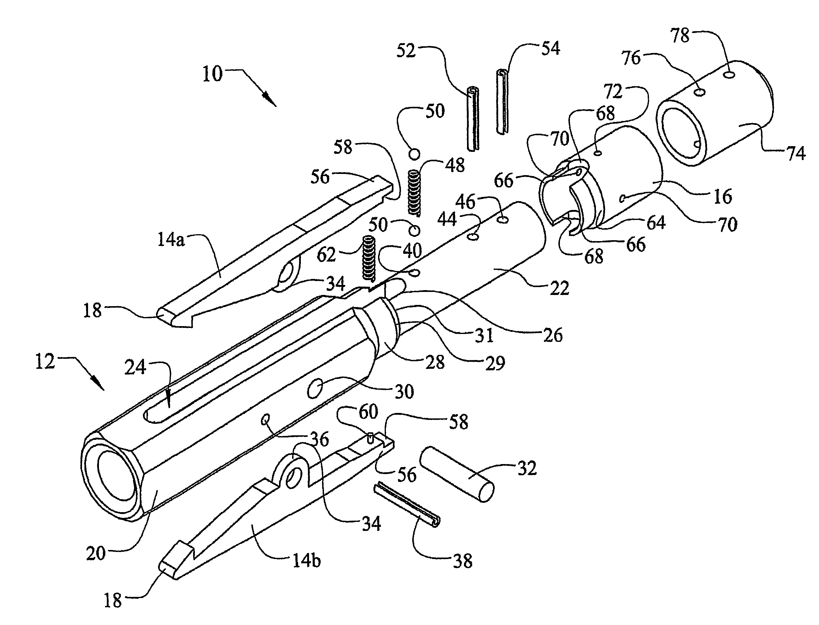
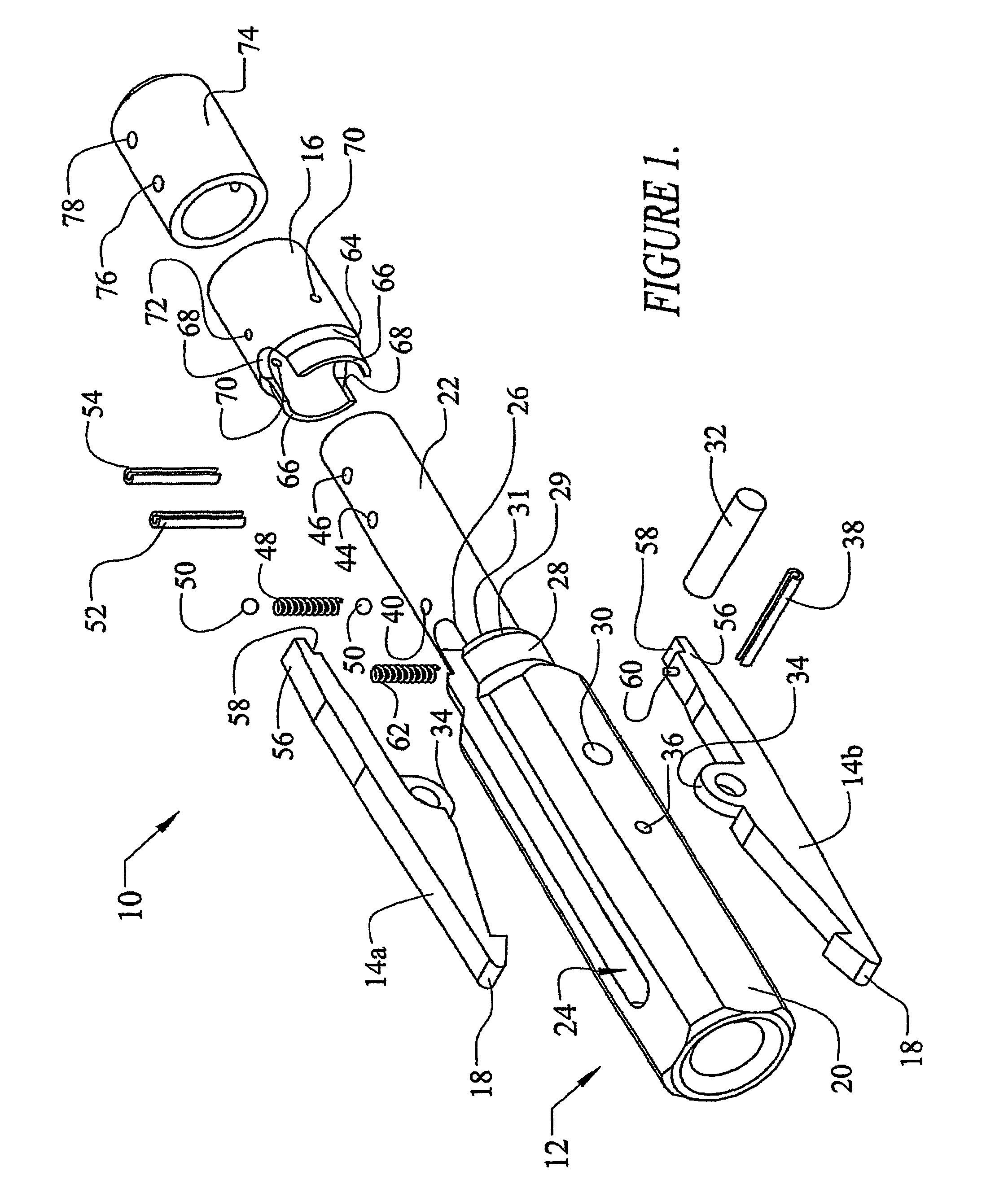
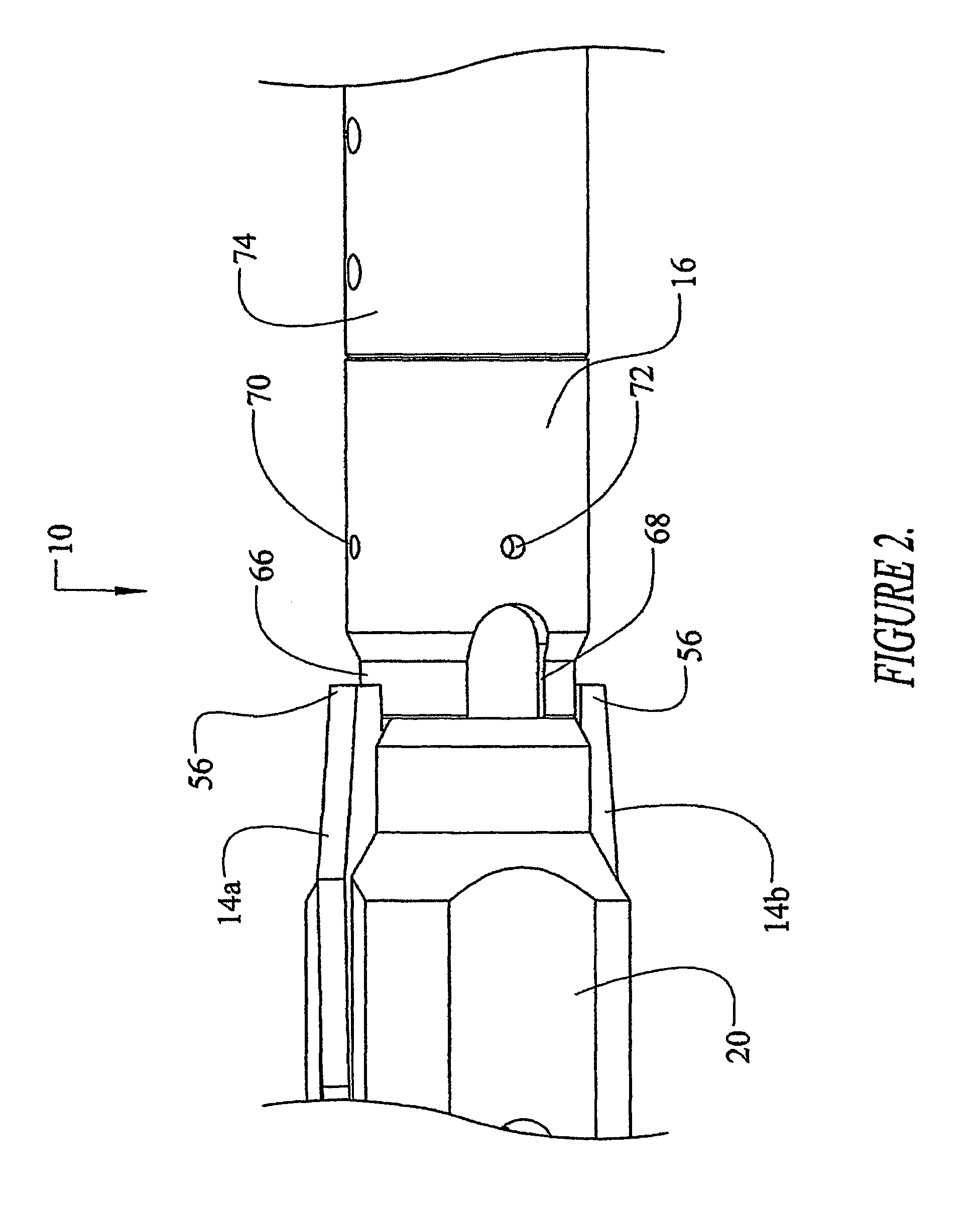
[0024]Referring to FIGS. 1–3 of the accompanying drawings, the lockable overshot 10 includes an elongated body 12, lifting dogs 14a and 14b (hereinafter referred to in general as “lifting dogs 14”) and a locking sleeve 16. The lifting dogs 14 are pivotally mounted to the body 12 and are provided with respective first ends 18 configured for latching a spearhead point therebetween. To this end, the lifting dogs 14 are of a substantially conventional configuration in which each first end 18 is provided with a hook-like formation which catches beneath a spearhead point (not shown). The locking sleeve 16 is retained on the body 12 and is switchable to locked state where the locking sleeve 16 locks the lifting dogs in the latched position preventing them from pivoting away from each other. In this embodiment the sleeve 16 or at least a portion thereof is seated between or inside the lifting dogs 14 to prevent them from pivoting to the ends 18 apart sufficiently to allow a latched spearhea...
PUM
 Abstract
Description
Claims
Application Information