Resonant magnetometer device

Active Publication Date: 2008-07-01
QINETIQ LTD
View PDF11 Cites 27 Cited by
  • Summary
  • Abstract
  • Description
  • Claims
  • Application Information

AI Technical Summary

Benefits of technology

[0043]The oscillatory member is conveniently attached to the substrate at a plurality of anchor point. Although stress relief portions may be formed in the vicinity of one or some of the anchor points, it is

Problems solved by technology

If an AC current is applied that has a frequency away from the resonant condition, the sensitivity of the device will be greatly diminished due to the loss of the Q amplification of the Lorentz force.
However, phase-lock loop circuits can introduce unwelcome phase noise be

Method used


Image

  • Resonant magnetometer device
  • Resonant magnetometer device
  • Resonant magnetometer device

Examples


Example

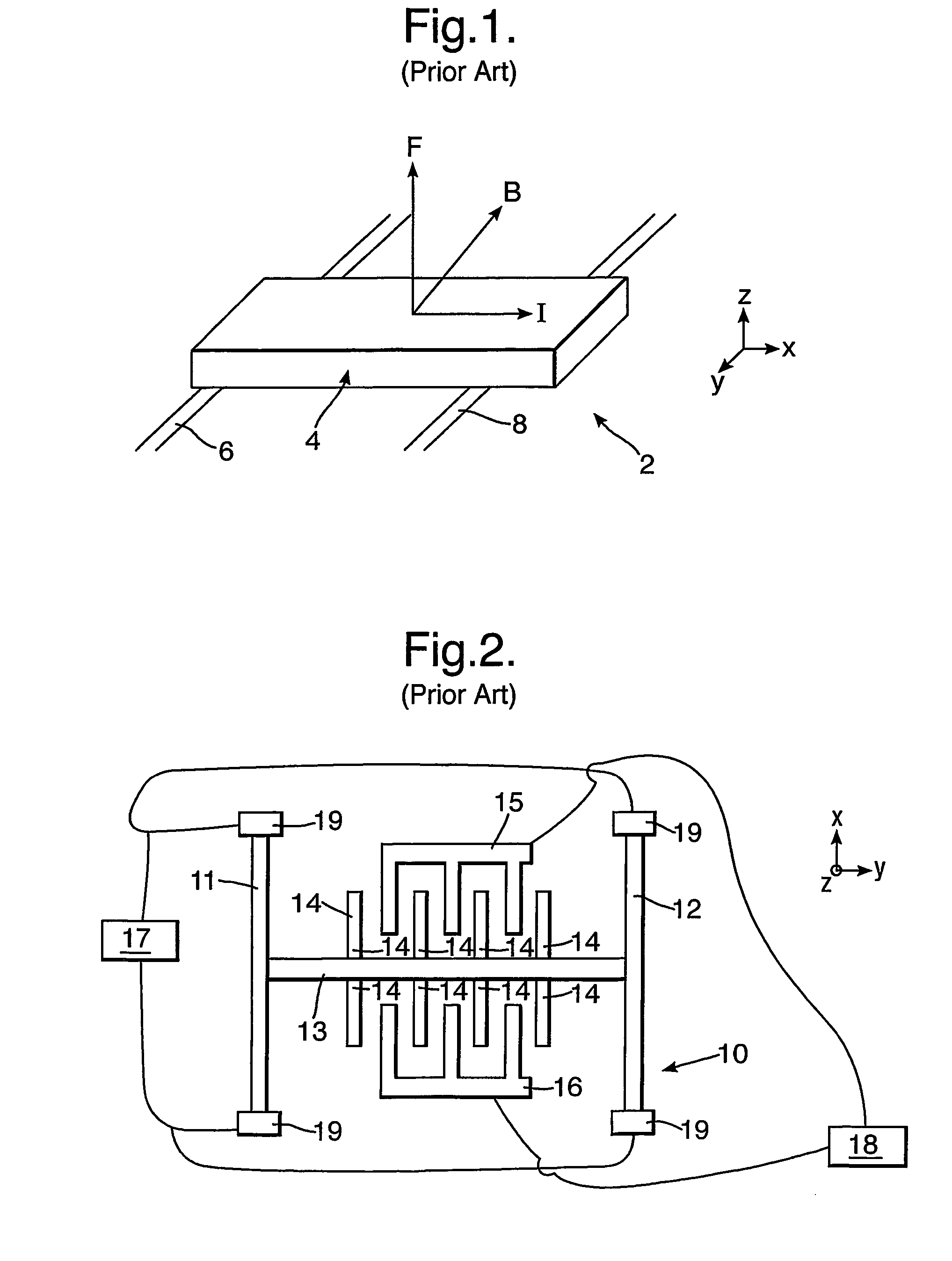
[0056]Referring to FIG. 1, a simple bar magnetometer 2 of the type described by Wickenden et al is shown. The magnetometer comprises a resonant bar 4 supported by a first electrode 6 and a second electrode 8. The first and second electrodes 6 and 8 are located at the nodal points of the fundamental mode of vibration of the bar 4.

[0057]An electrical current (I) passing through the bar 4 will, on interaction with a magnetic field (B), produce an out-of-plane Lorentz force (F). In use, an alternating current (AC) is applied to the bar 4 via the first electrode 6 and the second electrode 8. The frequency of the applied AC is matched to the resonant frequency of the resonant bar 4 thereby causing the device to resonate in the presence of a in-plane magnetic field (B). For a given applied current, the magnitude of resonance is indicative of the magnitude of the applied magnetic field. This Lorentz force effect forms the basis of operation of all resonant magnetometers.

[0058]Referring to F...


PUM


Abstract

A resonant magnetometer comprises a substrate having a member and circuitry for passing an alternating current (AC) through the member. The magnetometer is characterized in that a driver is also provided to impart a magnetic field independent oscillatory force to the member. Disclosed is a micro-electro mechanical systems (MEMS) implementation of a magnetometer.

Description

[0001]This application is the U.S. national phase of international application PCT / GB2004 / 004017 filed 21 Sep. 2004 which designated the U.S. and claims benefit of GB 0322236.1 filed 23 Sep. 2003, and GB 0323157.8 filed 3 Oct. 2003, and the entire contents of each of which are hereby incorporated by reference.BACKGROUND OF THE INVENTION[0002]1. Field of the Invention[0003]This invention relates to a magnetometer and in particular to a Micro-electro mechanical systems (MEMS) self-resonant magnetometer.[0004]2. Discussion of Prior Art[0005]Resonant magnetometers are well known. One of the earliest MEMS based resonant magnetometers is described by D. K. Wickenden et al in the paper “MEMS based resonating Xylophone Bar Magnetometers”, SPIE Conference Proceedings—Micromachined Devices and Components IV, SPIE Vol. 3514, pp 350-358, 1998. The Wickenden et al device comprises a surface micro-machined bar that is fixed to a pair of electrodes at the nodes of its first resonant mode. In use, ...

Claims


Application Information

Patent Timeline
IPC IPC(8): G01R33/02G01R33/028
CPCG01R33/0286G01R33/0283
Inventor BRUNSON, KEVIN MKING, DAVID O
Owner QINETIQ LTD
Why Eureka
Try Eureka