Electric motor fluid drainage interface

Inactive Publication Date: 2002-04-23
HAYSLETT RICHARD R
View PDF10 Cites 29 Cited by
  • Summary
  • Abstract
  • Description
  • Claims
  • Application Information

AI Technical Summary

Benefits of technology

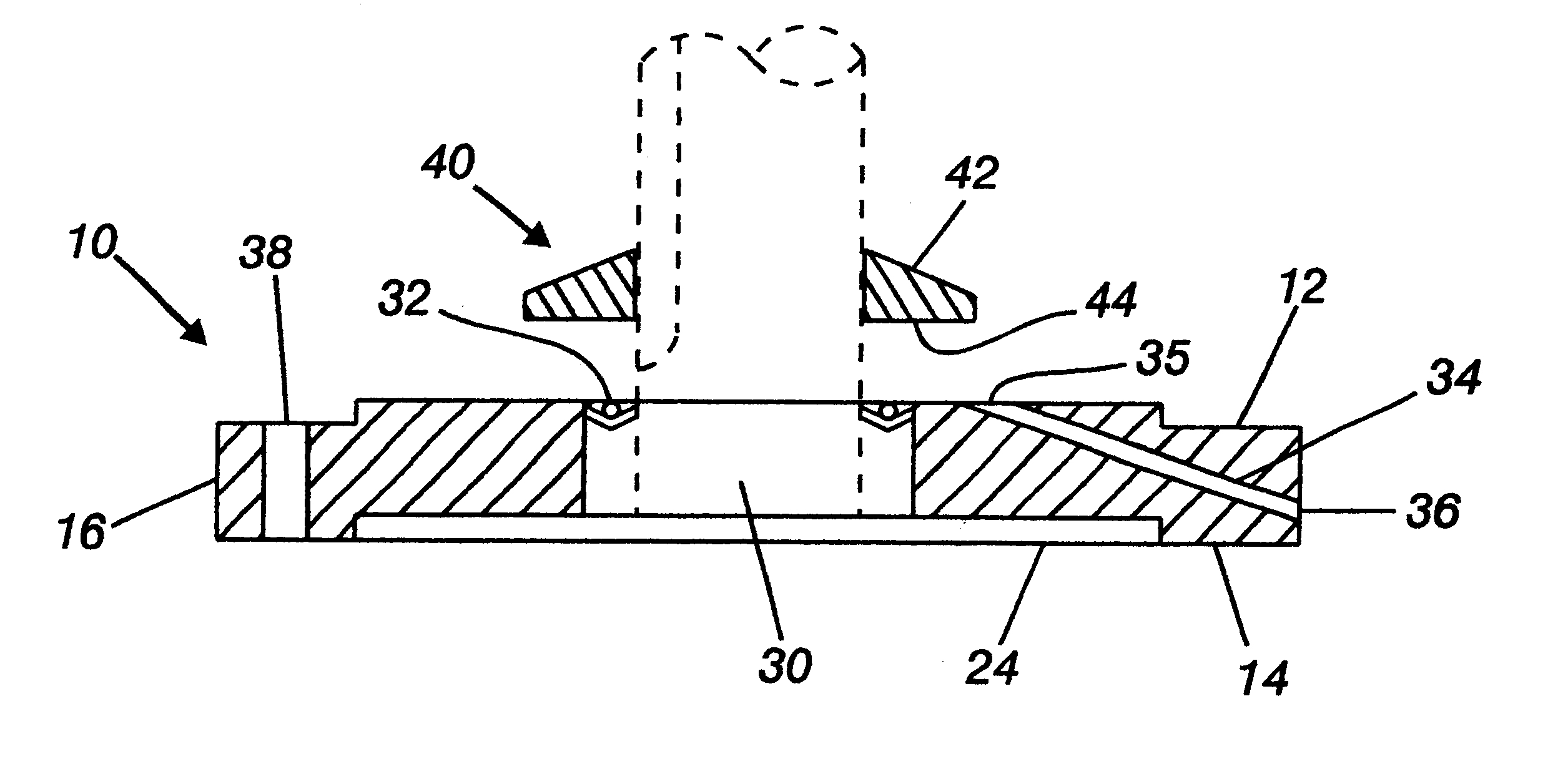
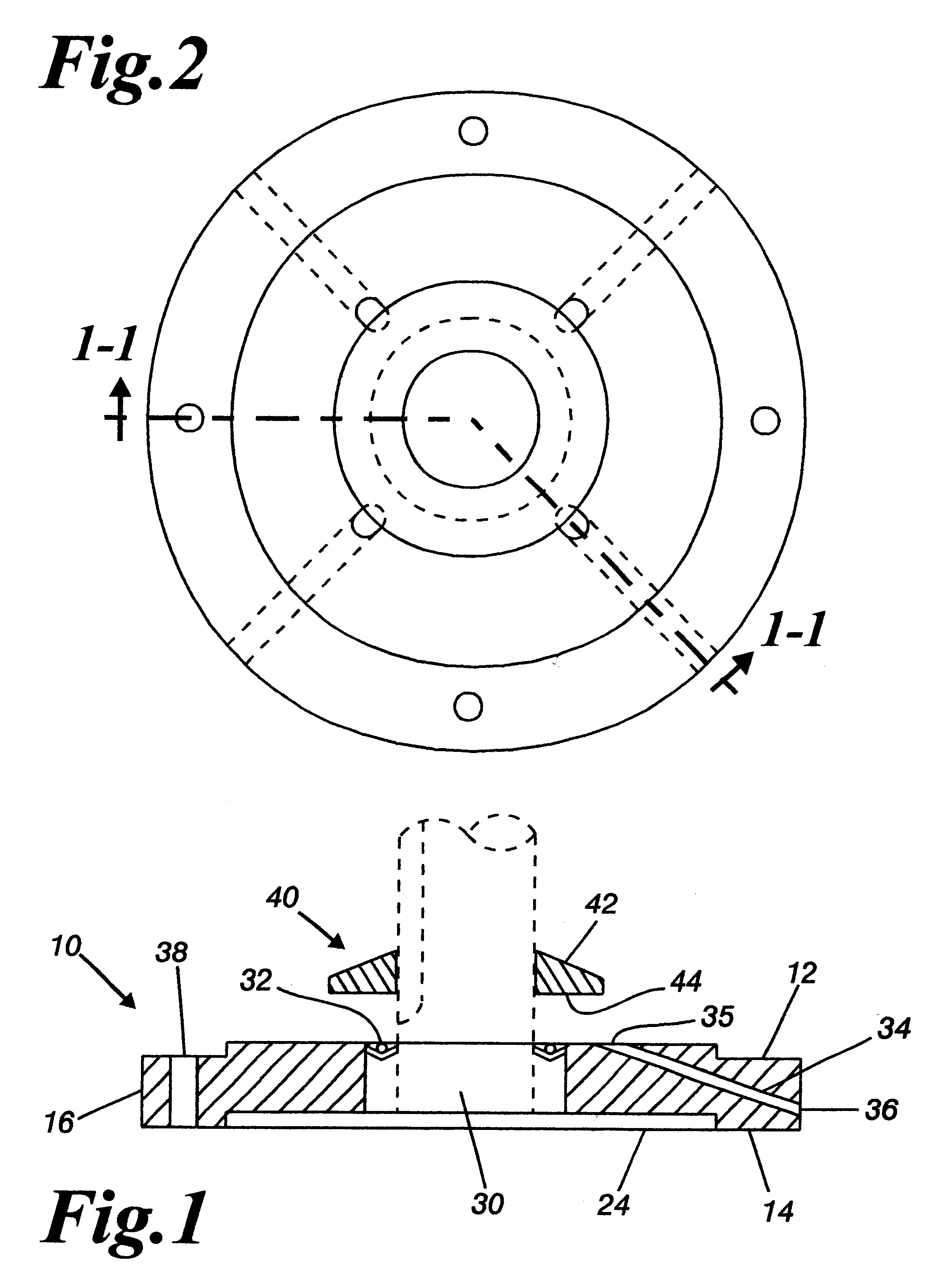
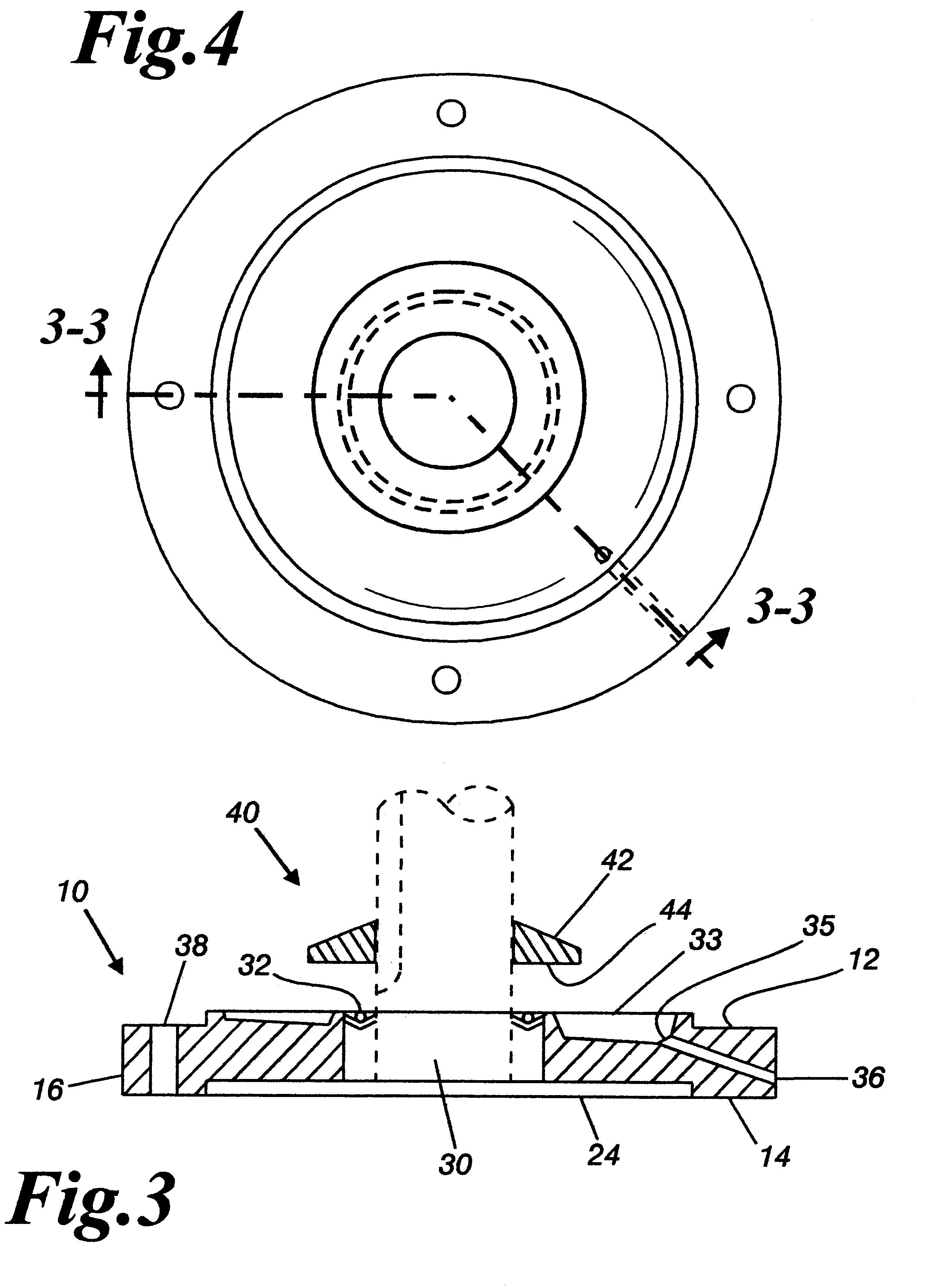
In operation, oil escaping from the driven equipment flows down the rotor shaft of the motor or falls directly upon the flinger 40. Rotation of the rotor shaft and flinger 40 during normal motor usage causes the oil to be projected outwardly, away from the rotor shaft. The oil then flows downward, by gravity, into the oil collection reservoir 50. If the motor is not in operation when the oil encounters the flinger 40, the oil will flow, by gravity, along the downwardly sloped upper surface 42 of the flinger 40 until the oil drops into the reservoir 50. The oil flows

Problems solved by technology

However, the '511 invention simply rests upon the endshield of the motor and does not facilitate the connection of the electric motor to other equipment.
First and foremost, leaking oil is not given the opportunity to enter the underlying electric motor, preventing probl

Method used


Image

  • Electric motor fluid drainage interface
  • Electric motor fluid drainage interface
  • Electric motor fluid drainage interface

Examples


Embodiment Construction

The invented interface may be manufactured to size specifications for use with any industrially applicable electric motor and motor driven device. However, most industrial applications utilize motor attachment means of standard size and shape. Of most significant note, C-Face flanges are a series of standardized flanges having a variety of sizes capable of mating electric motors with a wide range of motor driven equipment. The invented interface is specially suited for use with the C-Face flanges since the interface may by mounted directly upon a C-Face compatible motor and then directly mounted up into the C-Face compatible flange on industrial motor driven equipment.

By way of example, and not by way of limitation, sample interface dimensions as promulgated by the National Electrical Manufacturers Association (NEMA) are shown below.

Standardized sizes:

Corresponding dimensions for sample interfaces:

SUMMARY OF THE ACHIEVEMENT OF THE OBJECTS OF THE INVENTION

From the foregoing, it is re...


PUM


Abstract

An interface for mating a vertically oriented electric motor underneath a gearbox or other motor driven, fluid containing apparatus which substantially isolates the motor rotor and driven shaft from the external environment while facilitating the removal of leaking oil or other fluid from the area between the motor endshield and gearbox housing to the to the outside of the apparatus in order to prevent accidental oil penetration into the motor housing, the invented interface having a base plate component and a flinger component, wherein the flinger projects escaping oil away from the rotor shaft of the attached electric motor, which oil then drains through exit ports to the outside of the invented interface, such interface being connectable between electric motors and motor driven equipment through use of standardized C-face connection means.

Description

The present invention relates to a method and apparatus for a motor fluid drainage interface, and more particularly to apparatus and methods for production of an electric motor fluid drainage interface.Electric Motors are the prime movers for most industrial applications. In industry, most motors are used in conjunction with speed changing devices which change the speed or torque produced at the motor shaft to match the speed or torque required by the driven equipment such as pumps, fans, conveyors, etc.One of the most common speed changing devices is a speed reducer, or gearbox, which consist of a set of gears encased by a housing and partially immersed in lubricating oil. Oil is necessary in order to reduce friction between the gears and to allow the bearings in the gearbox to function properly. The oil leakage from the gearbox housing is prevented by oil seals.An electric motor may be connected to a gearbox in a variety of configurations, with the particular arrangement being dic...

Claims


Application Information

Patent Timeline
IPC IPC(8): H02K5/10H02K5/12H02K5/124H02K7/116
CPCH02K5/10H02K2205/09H02K7/116H02K5/124
Inventor HAYSLETT, RICHARD R.
Owner HAYSLETT RICHARD R
Why Eureka
Try Eureka