
Automatic injector

a technology of automatic injection and injector, which is applied in the direction of intravenous devices, infusion needles, other medical devices, etc., can solve the problems of fail-safe operation of the needle cover, and achieve the effect of preventing the rotation of the release pin and simplifying construction

Active Publication Date: 2006-02-09
MYLAN SPECIALTY
View PDF13 Cites 242 Cited by
  • Summary
  • Abstract
  • Description
  • Claims
  • Application Information

AI Technical Summary

Benefits of technology

"The present invention relates to an auto-injector for dispensing a predetermined dosage of medicament. The auto-injector includes a housing with an oval or elliptical shape that prevents it from rolling off a table or flat surface. The cartridge container is stored within the housing and includes a needle assembly with a plunger for dispensing the medicament. The needle cover is shielded from inadvertent exposure after use. The auto-injector has a first locking assembly that holds the needle cover in a locked position and a second locking assembly that holds the needle cover in a locked position. The first locking assembly is controlled to negligibly or minimally impede the motion of the cartridge during the injection operation to avoid any premature rupturing of the diaphragm within the cartridge and premature administering of the medicament. The needle cover is spring biased to cover the exposed needle after the first locking assembly is released. The second locking assembly includes at least one locking arm or wing connected to the cartridge container or the cover member. The needle cover is limited in its travel to prevent accidental exposure. The cartridge container may further include at least one ledge to limit the travel of the needle cover."

Problems solved by technology

Theoretically, the operation of the needle cover is fail safe because the cover will not deploy until after the needle penetrates the user.

Method used


Image

  • Automatic injector
  • Automatic injector
  • Automatic injector

Examples


Embodiment Construction

[0078] It should be appreciated that some of the components described herein are conventionally known in the broader aspects, as described in U.S. Pat. No. 4,031,893 (“the '893 patent”) hereby incorporated by reference in its entirety, and thus not described in unnecessary detail here. It should also be appreciated that known modifications or variations to the '893 patent can apply equally to the auto-injector of the present invention as will be described below. These modifications or variations include embodiments described in U.S. Pat. Nos. 4,226,235; 4,329,988; 4,394,863; 4,723,937; and U.S. Ser. Nos. 09 / 985,466; 10 / 285,692, each of which is incorporated by reference in its entirety for the full teachings therein.

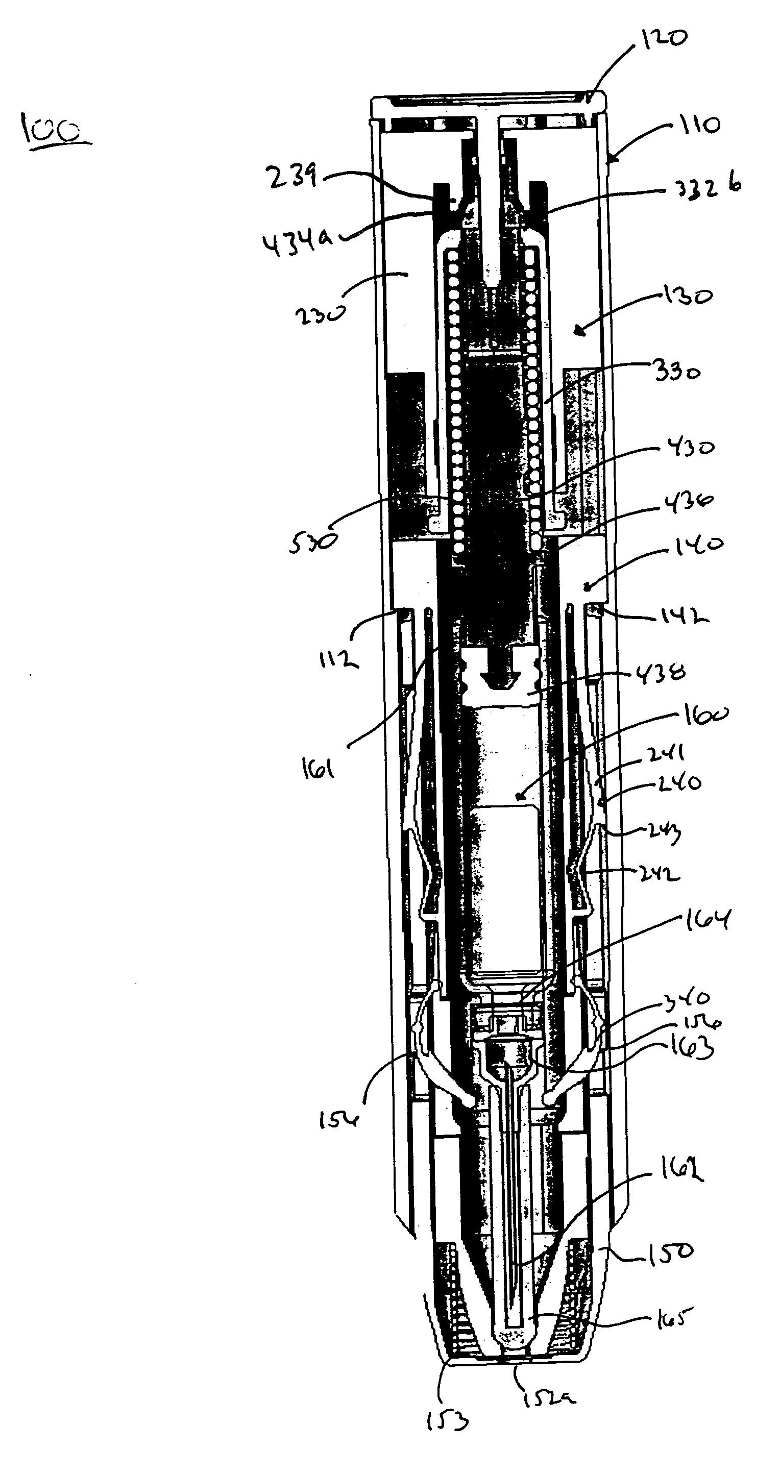
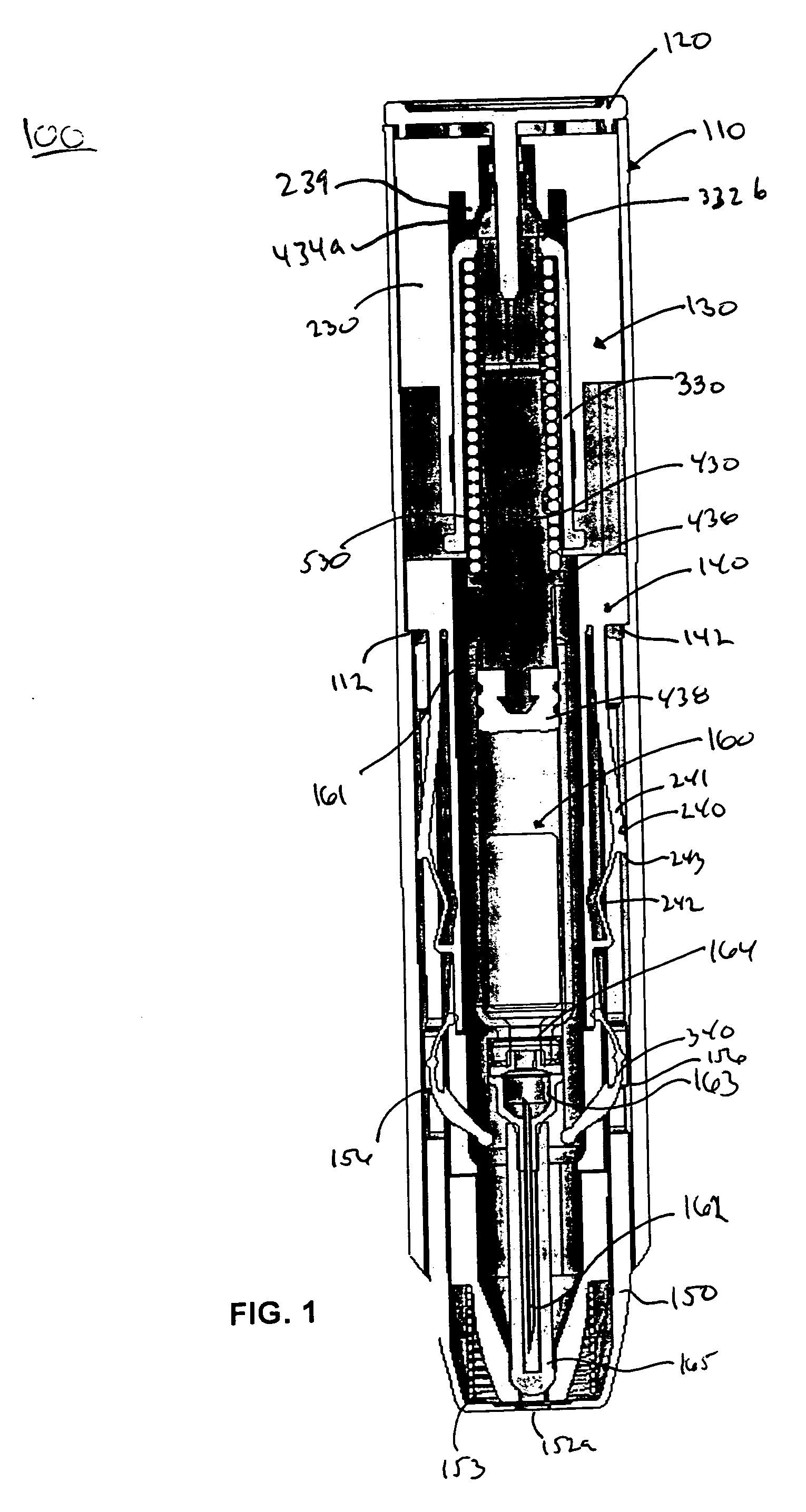
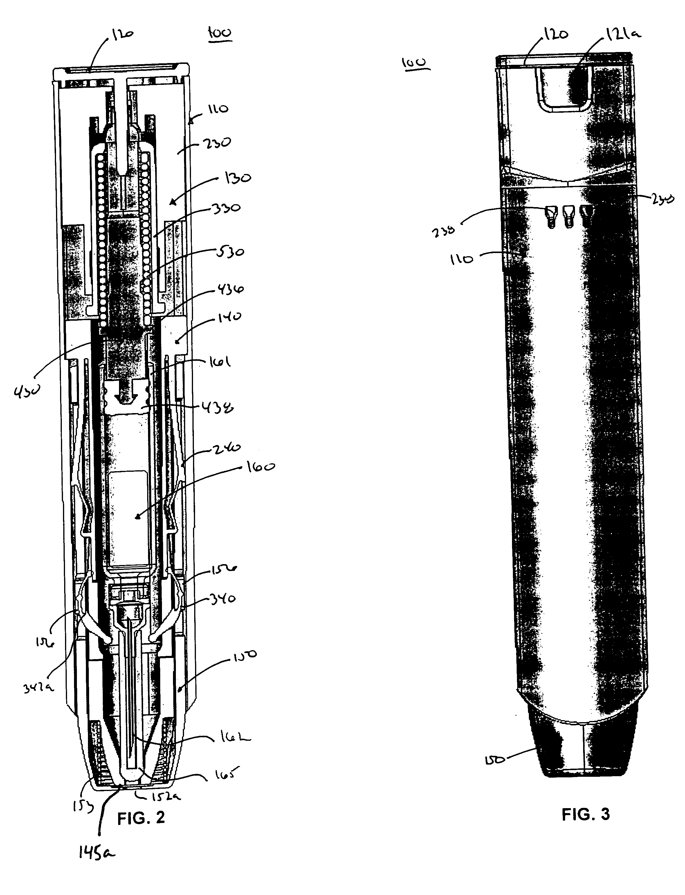
[0079] An auto-injector 100 of the present invention will now be described in greater detail in connection withFIGS. 1-59. The auto-injector 100 includes an outer body 110, a release pin 120, a power pack 130, a cartridge container 140, a needle cover 150 and a cartridg...


PUM


Abstract

An auto-injector for dispensing a predetermined dose of medicament is disclosed. The auto-injector includes a needle cover that is configured to move from a retracted position to an extended locked position. The auto-injector includes a first locking assembly to hold the needle cover in a locked retracted position and a second locking assembly to hold the needle cover in a locked extended position.

Description

CROSS REFERENCE TO RELATED APPLICATION [0001] The application relates to and claims priority to U.S. Provisional Patent Application No. 60 / 599,054, filed on Aug. 6, 2004, which is incorporated herein in its entirety specifically by reference.BACKGROUND OF THE INVENTION [0002] 1. Field of the Invention [0003] The present invention relates to an automatic injector or auto-injector for delivering medicament to an injection site. In particular, the present invention is directed to an auto-injector having a needle cover mechanism to prevent a user from coming into contact with the needle of the auto-injector after use. The needle cover mechanism is held in a locked position prior to activation of the auto-injector. After injection, the needle cover mechanism is held in a locked deployed position such that the user cannot access the needle. [0004] The present invention is also directed to an auto-injector having a power pack containing a one-piece molded collet. The molded collet reduces ...

Claims


Application Information

Patent Timeline
Patent Type & Authority Applications(United States)
IPC IPC(8): A61M5/00
CPCA61M2005/2013A61M5/2033A61M5/3271A61M2005/3247A61M5/3129A61M5/326A61M2005/206A61M5/2459A61M2005/2073A61M5/20A61M5/3245A61M5/31596A61M2005/3126A61M2205/586
Inventor YOUNG, MATTHEW EGERTONRAVEN, SOPHIE REBECCAMURPHY, MARTIN JOSEPHHURLSTONE, CHRISTOPHER JOHNDAINTREY, JOSEPH WILLIAMROCHFORD, CRAIG MALCOLMKIRKWOOD, STEPHEN PHILIPMATHEWS, COLIN JAMESHILL, ROBERT L.WILMOT, JOHN GLYNDWR
Owner MYLAN SPECIALTY
Learn More