Compressed porous materials suitable for implant

a porous material and implant technology, applied in the field of surgical devices, can solve the problems of high harvest site morbidity, insufficient quantity of graft material for autografts removed from patients, and high use of bone grafts, and achieve the effect of reducing porosity and increasing the surface area of porous matrix

Active Publication Date: 2010-05-25
DSM IP ASSETS BV
View PDF21 Cites 217 Cited by
  • Summary
  • Abstract
  • Description
  • Claims
  • Application Information

AI Technical Summary

Benefits of technology

[0020]Another aspect of this invention relates to controlled stretching and molding of a porous matrix material. Heating to temperatures above the glass transition temperature allow the porous polymer to soften and contract. If contraction is prevented and a force in a new direction is applied, the malleable polymer can be stretch to the extent that the porosity can collapse allowing the porous matrix to be pressed into or over a mold. Cooling at this time will lock in the new shape. The area of polymer that has been shaped is different than the unaltered areas. This is due to the forced alignment of the polymer partitions. Molds may be tailored to impart anisotropic effects at discrete locations throughout the implant, through creating areas of higher flow (i.e., more stretching) as well as areas of very low flow. Therefore, properties may be tailored by location and degree. Unlike the compressing method described above, this method has the ability to increase the surface areas within the porous matrix as the porosity is reduced.

Problems solved by technology

Unfortunately, the use of bone grafts presents several disadvantages.
Additionally, autografts removed from a patient may not yield a sufficient quantity of graft material.
Harvesting bone is also associated with high rates of harvest site morbidity and can increase the risk of infection and blood loss.
Alternatively, allografts obviate the need for bone harvesting, but have inconsistent mechanical properties.
Allografts can also transmit diseases or cause infections, and they have unpredictable and slow fusion rates.
Autografts and allografts alone may not provide the stability required to withstand spinal loads and are subject to collapse or failure due to a lack of strength.
In the mid-1970's, Bagby found the clinical results of harvest site morbidity to be unacceptable.
Metal interbody fusion devices are a permanent foreign body and are difficult to remove during revision surgery.
Due to the difference in mechanical properties of bone and metal, the main concern of metal interbody fusion devices is stress-shielding, which may cause bone resorption or osteopenia.
Although these devices have demonstrated an ability to facilitate fusion, a sufficient fusion is not always achieved between the bone grafts housed within the cage and the vertebral endplates.
Achieving a complete bony union in the middle portion of the cage has been particularly problematic.
Clinical fusion outcomes may be difficult to assess with metallic interbody fusion devices due to the artifacts and scattering during postoperative CT or MRI scans.
Often a complete bony union cannot be seen, making fusion results unreliable.
Long-term results with metal and carbon fiber interbody fusion devices are unknown due to the relatively recent development of the implants.
Metal cages have been known to fatigue and will eventually fail if a solid bony fusion is not achieved.
The elasticity of the porous materials is similar to live bony tissue; however, most of the disadvantages associated with carbon fiber and solid metal internal fixation devices still apply to the porous nickel-titanium and carbon-tantalum alloy materials.
They have the compressive strength to withstand and carry the spinal axial loads; however, they have a modulus of elasticity similar to bone, which limits stress-shielding.
Due to the brittle nature of ceramic materials, particularly as degradation occurs, the disclosed materials may not withstand the axial loads or cyclic loading of the implant site (e.g., spine) without fracture, collapse, and ultimately device failure.
The implant design with the resorbable inner core does not allow for the use of a bone graft within the device.
A high strength outer shell may provide sufficient support; however, it brings concomitant property mismatch with natural bone.
Bioceramics as used to form the outer shell are brittle and may fracture under high spinal loads.
If the bioresorbable layer and bone graft degrade before fusion can occur, the non-resorbable support may cause stress-shielding.
Depending on the thickness of the bioresorbable layer, complete degradation of the layer may cause a great decrease in disc space height.
The device is not porous, consequently limiting bone ingrowth.
The disclosed device will slowly degrade and lose strength over time with complete resorption predicted to occur by one year.
Clinically, complete fusion and bony union may take longer than one year in unstable patients.
If fusion of the endplates through the disk space does not occur, the short-term resorption of the device may lead to collapse of the disk space.
Autografts require bone graft harvesting, which causes postoperative pain and morbidity at the harvest site.
Allografts put the patient at risk for infection or transmitted diseases.
Metal cages can cause stress-shielding and make fusion assessment difficult.

Method used


Image

  • Compressed porous materials suitable for implant
  • Compressed porous materials suitable for implant
  • Compressed porous materials suitable for implant

Examples


example 1

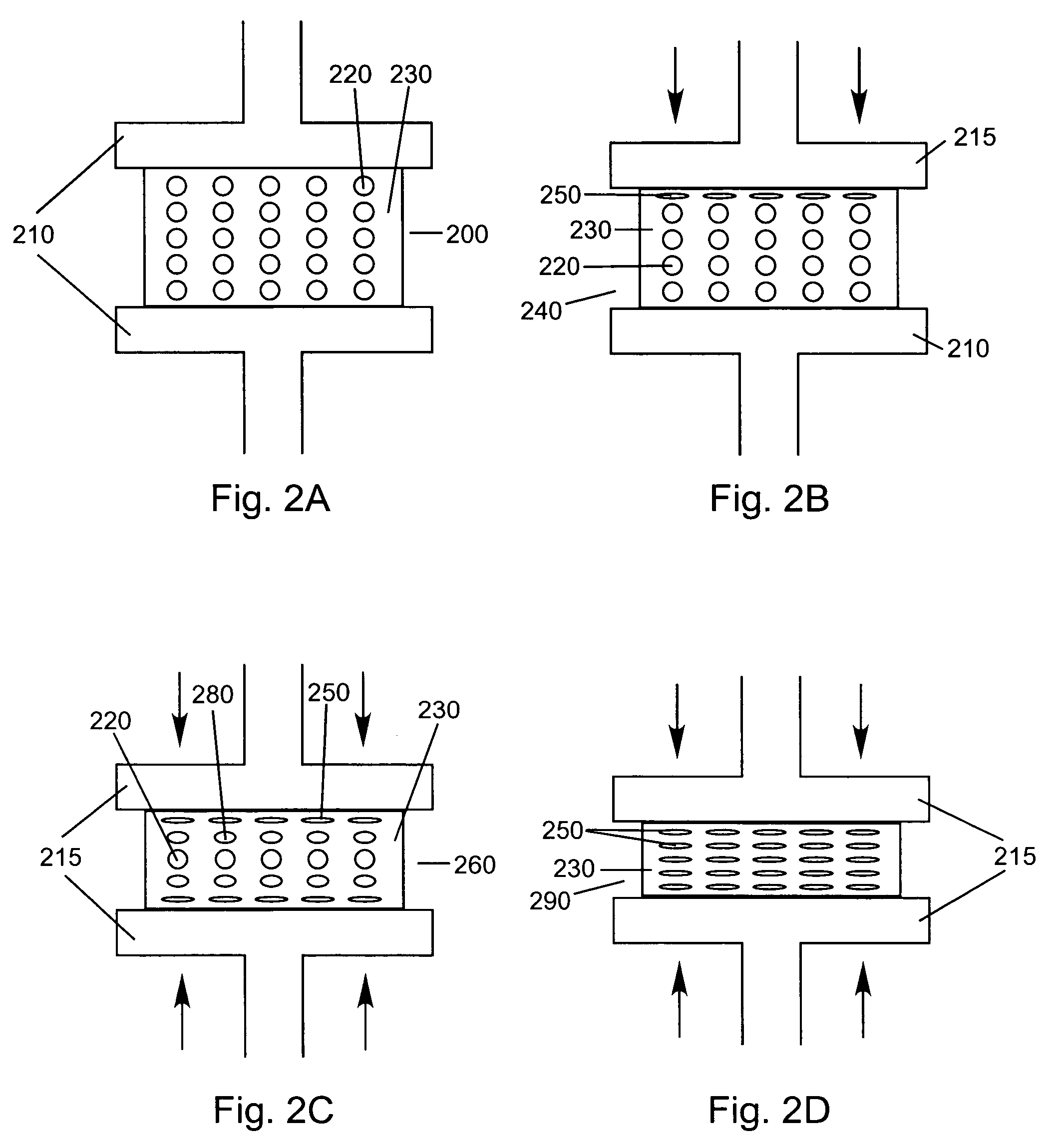
[0104]The objective of this example is to compare the physical properties of different Poly-1-lactide (PLA) porous matrix materials after being compressed 0, 40, 60, and 80% of its original height. Static axial compression tests were performed to measure the maximum compressive loads of the porous matrix materials after being compressed to different percentages of their original height. The compression tests will demonstrate the compressed material's mechanical properties can be altered and controlled over a wide range of possible values. The final properties of the compressed material are determined by the properties of the starting material and the amount of compression used. The final product is a material that has tensile and compressive strengths similar to that of non-porous polymer yet is not as stiff or subject to failure by cracking as non-porous polymer. The mechanical and porosity tests will assure a device fabricated from compressed porous matrix material (e.g., a spinal...

example 2

[0110]While Example 1 demonstrated that PLA porous matrix materials could be compressed, this example serves to illustrate that porous matrix materials made of different polymers can also be compressed and will compare the physical properties of the two compressed materials. Polylactide / Poly ε-Caprolactone (PLA / PCL) and Poly(desaminotyrosyl-tyrosine ethyl carbonate) (PDTE) Carbonate were used to create two different porous matrix materials. The compression, porosity, and wettability tests described in Example 1 were used to test these materials.

[0111]Static axial compression, wettability, and porosity tests were conducted as described in the EXAMPLE 1.

[0112]Before compression, the porosities of the PLA / PCL and PDTE Carbonate were 92% and 94%, respectively. Up to 40% compression, the materials show little to no change in porosity. At 80% compression, the more brittle porous material (PDTE Carbonate) had a porosity of 73% compared to 66% porosity for the PLA / PCL material. It should be...


PUM

PropertyMeasurementUnit
porositiesaaaaaaaaaa
diameteraaaaaaaaaa
porositiesaaaaaaaaaa

Abstract

A high strength porous polymeric material manufactured by a compression process is disclosed. The material results in a network of interconnected collapsed pores, which forces thin overlapping walls and passages to be created. The network provides permeable access for fluid migration throughout the material. The strength and / or permeability are advantageous for medical devices and implants.

Description

BACKGROUND OF THE INVENTION[0001]The present invention relates to surgical devices for stabilizing and / or fusing adjacent bone structures, and, more particularly, to surgical devices for stabilizing and / or fusing the spine and for implantation between the vertebrae, including the intradiscal space. Generally, this invention concerns internal fixation devices, particularly spinal fusion and related implants.[0002]Spinal degenerative diseases (e.g., stenosis, disc disease, spondylosis, etc.) trauma, aging, or a herniated disc can cause compression in the spine thus applying pressure to the nerve roots and / or spinal cord. The compression produces progressive pain, loss of movement and sensation, and sometimes, permanent disability. Spinal fusion is among the standards of care for surgical decompression and stabilization of the spine. Fusion, known also as arthrodesis, is accomplished by the formation of an osseous bridge between adjacent motion segments. The goals of spinal surgery inc...

Claims


Application Information

Patent Timeline
Patent Type & Authority Patents(United States)
IPC IPC(8): A61F2/02A61F2/28A61F2/44A61L27/00A61L27/56
CPCA61B17/0642A61L27/56A61B17/846A61B17/866A61F2/3094A61F2002/2817A61F2002/30014A61F2002/30032A61F2002/30036A61F2002/30062A61F2002/30235A61F2002/30563A61F2002/30578A61F2002/30677A61F2002/30904A61F2002/3092A61F2002/30971A61F2310/00293A61F2310/0097A61B17/7059
Inventor RINGEISEN, TIMOTHY A.TURNER, AMANDADEMEO, JOSEPHHEARN, PATRICK E.MCDADE, ROBERT L.
Owner DSM IP ASSETS BV
Why Eureka
Try Eureka