Method of in situ formation of translumenally deployable heart valve support

a technology of heart valve and in situ formation, which is applied in the field of medical methods and devices, can solve the problems of affecting the function of the heart valve, and affecting the function of the heart valve, and achieves the effect of increasing the rigidity of the support component and enabling minimally invasive procedures on the valv

Inactive Publication Date: 2008-01-17
DIRECT FLOW MEDICAL INC
View PDF98 Cites 94 Cited by
  • Summary
  • Abstract
  • Description
  • Claims
  • Application Information

AI Technical Summary

Benefits of technology

[0032] Yet another embodiment of the present invention comprises a temporary heart valve catheter, for enabling minimally invasive procedures on a valve in a beating heart. The catheter includes an elongate, flexible catheter body, having a proximal end and a distal end, a valve on the distal end, the valve comprising an inflatable structure; and at least one link between the catheter and the valve to prevent detachment of the valve from the catheter.
[0033] Another embodiment of the present invention comprises a method of in situ formation of a prosthetic valve support. A prosthetic valve is attached to a flexible support component which is incapable of retaining the valve at a functional site in the arterial vasculature. The support component extends both proximally and distally of the base of the valve. The valve is positioned at the site. The flexible support component is supplemented to increase the rigidity of the support component sufficiently to retain the valve at the site.
[0041] In accordance with a another embodiment of the present invention, there is provided a temporary heart valve catheter, for enabling minimally invasive procedures on a valve in a beating heart. The catheter comprises an elongate flexible catheter body, having a proximal end and a distal end. A valve is carried by the distal end. At least one link is provided between the catheter and the valve to prevent detachment of the valve from the catheter. The valve may be supported by a support frame, which is connected to a pull wire or wires extending axially throughout the length of the catheter. Axial tensioning of the pull wire relative to the catheter body deploys the valve into its functional configuration. Proximal retraction of the pull wire causes the valve to reduce in cross section and draw into the distal end of the catheter, such as for placement or removal. The link may comprise a connection between the pull wire and a valve support.

Problems solved by technology

Patient with cardiac disease resulting in slight limitation of physical activity.
Ordinary physical activity results in fatigue, palpitation, dyspnea, or anginal pain.
Patients with cardiac disease resulting in marked limitation of physical activity.
Patients with cardiac disease resulting in inability to carry on any physical activity without discomfort.
If any physical activity is undertaken, discomfort is increased.
Access to these sites generally include a thoracotomy or a sternotomy for the patient and include a great deal of recovery time.
Although valve repair and replacement can successfully treat many patients with valvular insufficiency, techniques currently in use are attended by significant morbidity and mortality.
Despite the many years of effort, and enormous investment of entrepreneurial talent and money, no stent based heart valve system has yet received regulatory approval, and a variety of difficulties remain.
For example, stent based systems have a fixed rigidity even in the collapsed configuration, and have inherent difficulties relating to partial deployment, temporary deployment, removal and navigation.

Method used


Image

  • Method of in situ formation of translumenally deployable heart valve support
  • Method of in situ formation of translumenally deployable heart valve support
  • Method of in situ formation of translumenally deployable heart valve support

Examples


Embodiment Construction

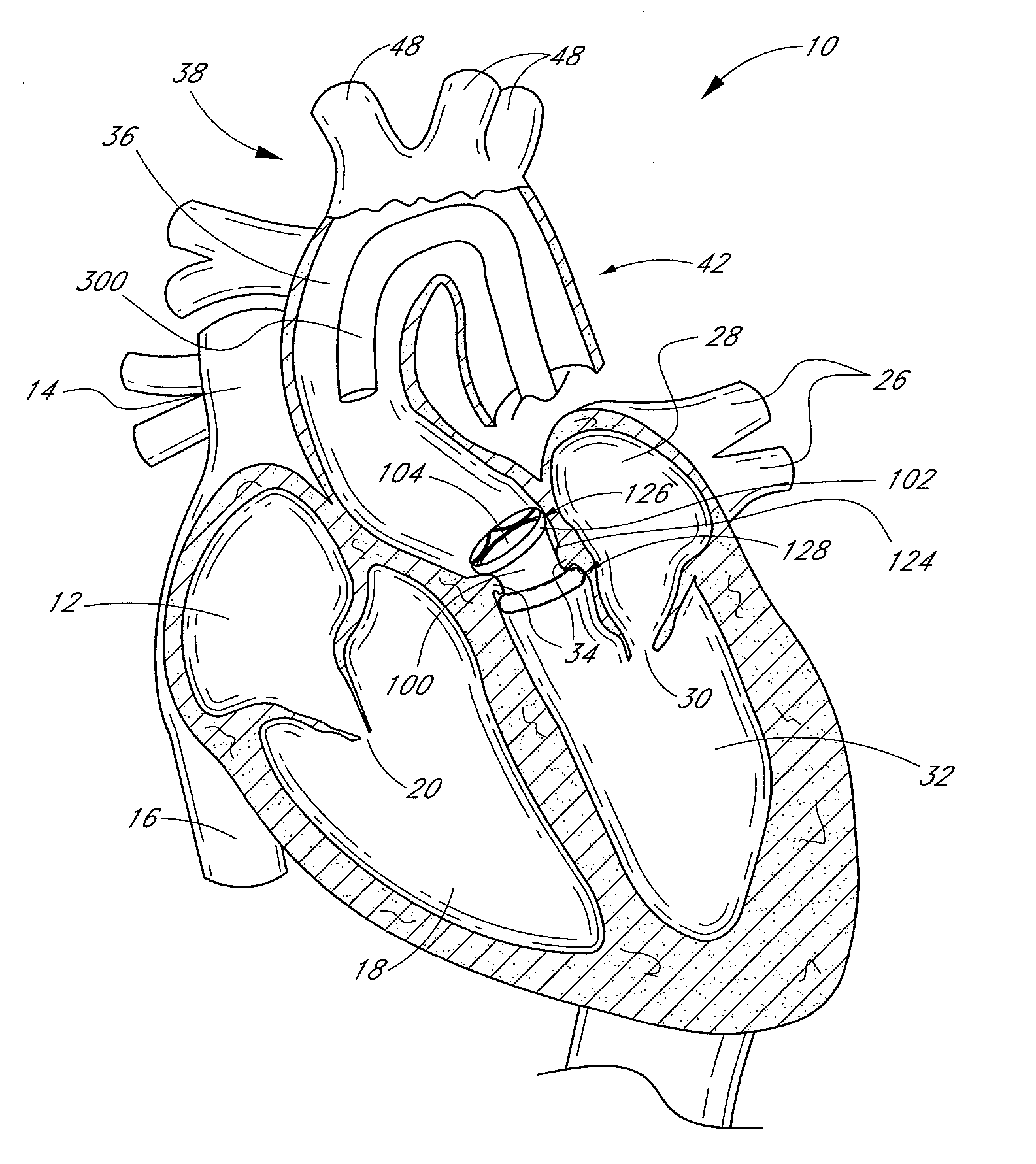
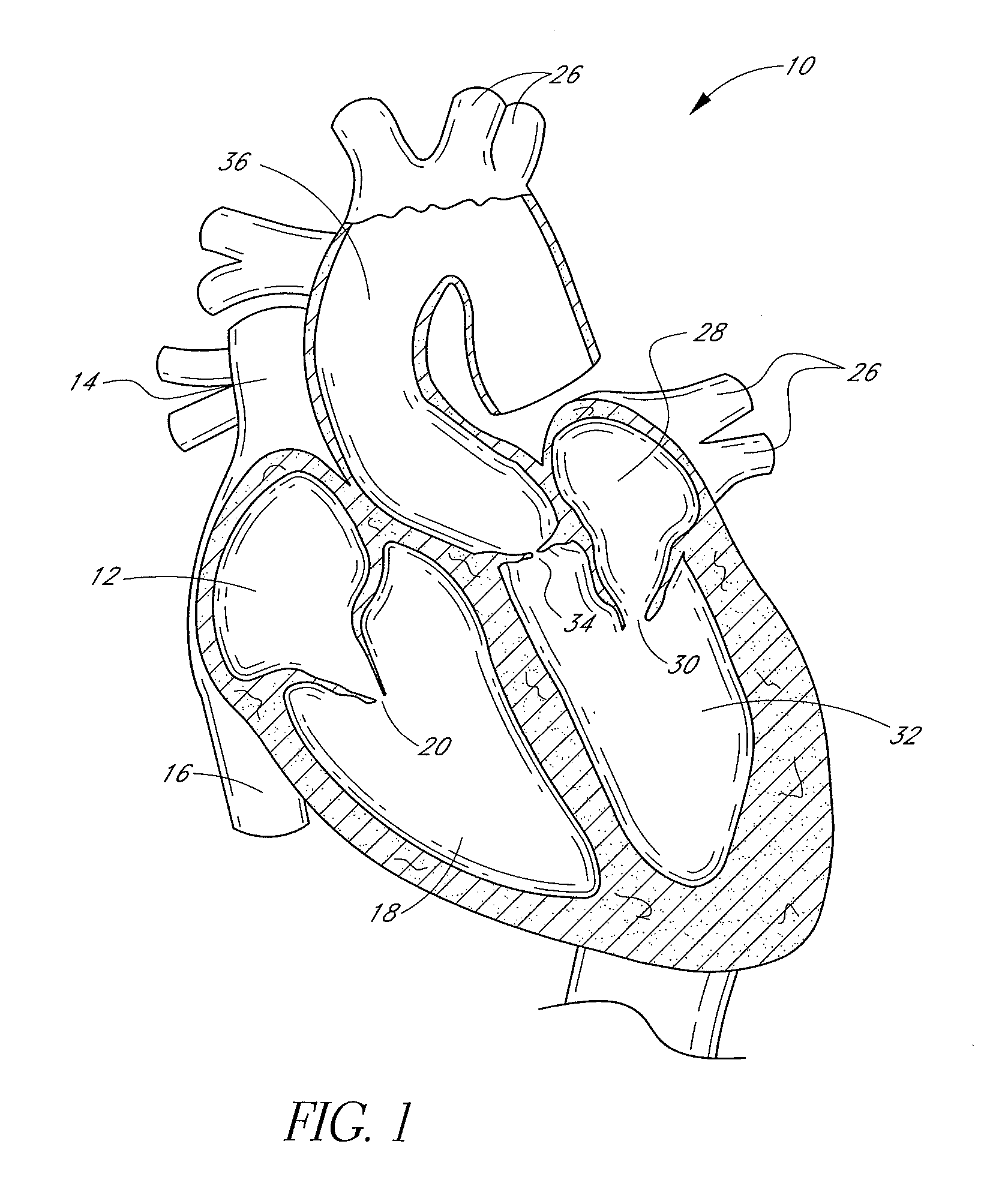
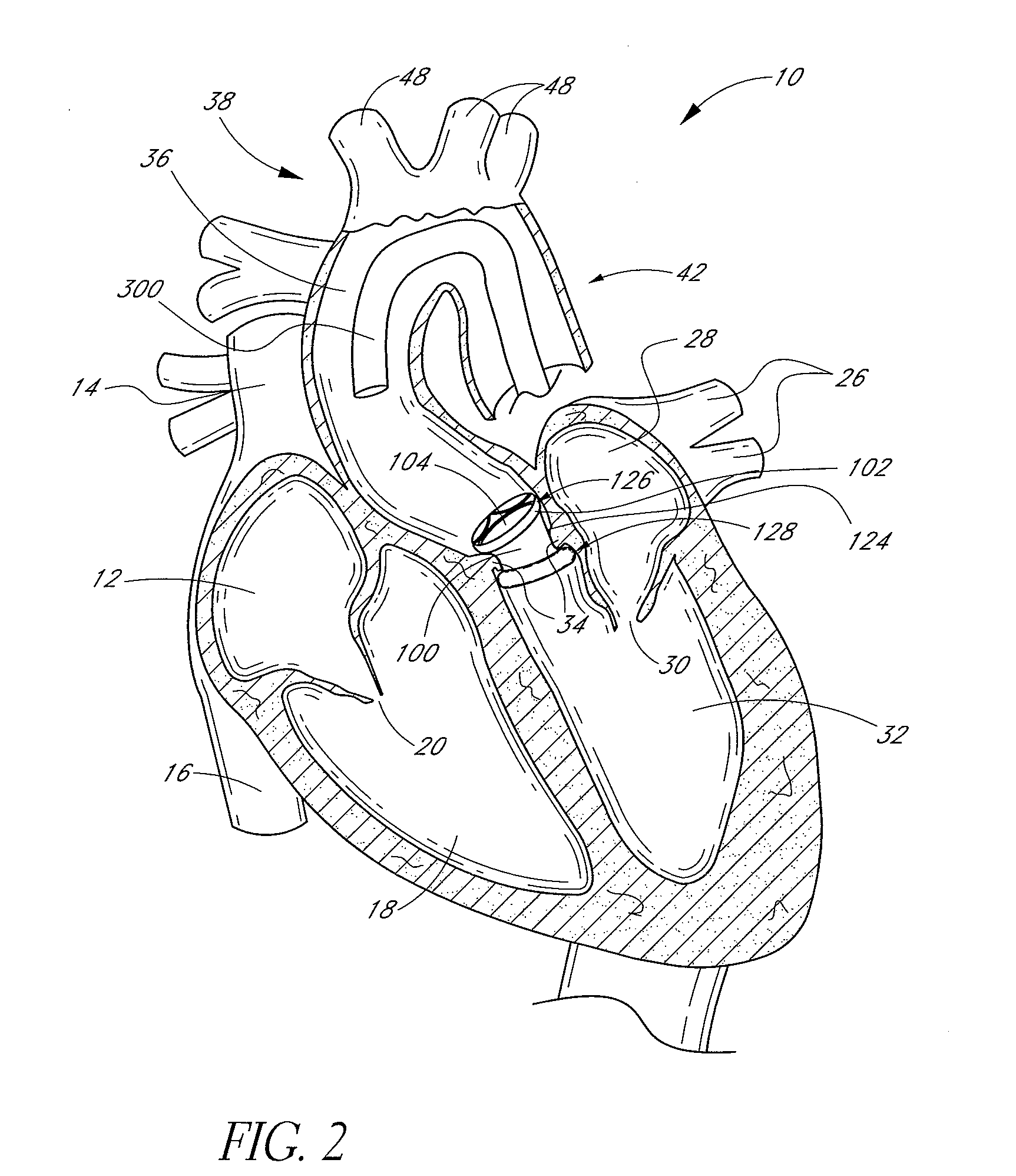
[0138]FIG. 1 is a schematic cross-sectional illustration of the anatomical structure and major blood vessels of a heart 10. Deoxygenated blood is delivered to the right atrium 12 of the heart 10 by the superior and inferior vena cava 14, 16. Blood in the right atrium 12 is allowed into the right ventricle 18 through the tricuspid valve 20. Once in the right ventricle 18, the heart 10 delivers this blood through the pulmonary valve 22 to the pulmonary arteries 24 and to the lungs for a gaseous exchange of oxygen. The circulatory pressures carry this blood back to the heart via the pulmonary veins 26 and into the left atrium 28. Filling of the left atrium 28 occurs as the mitral valve 30 opens allowing blood to be drawn into the left ventricle 32 for expulsion through the aortic valve 34 and on to the body extremities through the aorta 36. When the heart 10 fails to continuously produce normal flow and pressures, a disease commonly referred to as heart failure occurs.

[0139] One cause...


PUM


Abstract

A method of implanting a prosthetic valve within the heart comprises translumenally advancing a prosthetic valve comprising an inflatable structure to a position proximate a native valve of the heart. A first chamber of the inflatable structure is inflated and then, independently, a second chamber of the inflatable structure is inflated.

Description

PRIORITY INFORMATION [0001] This application is a continuation of U.S. patent application Ser. No. 11 / 112,978, filed May 5, 2005, which claims the priority benefit of (1) U.S. Provisional Application 60 / 568,402, filed May 5, 2004, (2) U.S. Provisional Application 60 / 572,561, filed May 19, 2004, (3) U.S. Provisional Application 60 / 581,664, filed Jun. 21, 2004, (4) U.S. Provisional Application 60 / 586,054, filed Jul. 7, 2004, (5) U.S. Provisional Application 60 / 586,110, filed Jul. 7, 2004, (6) U.S. Provisional Application 60 / 586,005, filed Jul. 7, 2004, (7) U.S. Provisional Application 60 / 586,002, filed Jul. 7, 2004, (8) U.S. Provisional Application 60 / 586,055, filed Jul. 7, 2004, (9) U.S. Provisional Application 60 / 586,006, filed Jul. 7, 2004, (10) U.S. Provisional Application 60 / 588,106, filed Jul. 15, 2004, (11) U.S. Provisional Application 60 / 603,324, filed Aug. 20, 2004, (12) U.S. Provisional Application 60 / 605,204, filed Aug. 27, 2004 and (13) U.S. Provisional Application 60 / 610,...

Claims


Application Information

Patent Timeline
Patent Type & Authority Applications(United States)
IPC IPC(8): A61F2/24A61B17/04A61B17/064A61B17/068A61F2/02A61F2/06
CPCA61B17/04A61F2230/008A61B17/0644A61B17/068A61B17/0682A61B2017/00243A61B2017/00867A61B2017/0404A61B2017/0406A61B2017/06019A61B2017/0647A61F2/2409A61F2/2415A61F2/2418A61F2/2427A61F2/2439A61F2002/061A61F2002/068A61F2002/30583A61F2002/30672A61F2210/0085A61F2220/0016A61F2250/0003A61F2250/0059Y10S623/904A61F2220/0008A61F2220/005A61F2220/0066A61F2220/0075A61F2230/0054A61F2230/0078A61B17/0469A61F2250/0021A61F2/013A61F2/2436A61F2/014
Inventor LASHINSKI, RANDALL T.BISHOP, GORDON B.
Owner DIRECT FLOW MEDICAL INC
Why Eureka
Try Eureka