Stentless aortic valve replacement with high radial strength

Inactive Publication Date: 2007-01-04
SPEYSIDE MEDICAL LLC
View PDF98 Cites 63 Cited by
  • Summary
  • Abstract
  • Description
  • Claims
  • Application Information

AI Technical Summary

Benefits of technology

[0005] The present invention is based on the task of solving the problem configuring a device for replacement of an aortic or other valve on the human heart or peripheral vascular system by a minimally invasive technique. A device with a high radial strength may provide an ideal implant for heavily calcified aortic valves. Conventional treatment includes surgical replacement or a percutaneous balloon valvuloplasty. The second option is an insertion of a balloon catheter to the calcified aortic valve and inflation to dilation of the native valve to push the calcium aside. Though this technique is successful acutely, the restinosis rates are shown to be about 80% at twelve months. Some physicians in Europe believe this to be a technique to use in maintaining aortic flow in patients with out a surgical option. By this technique a patient may be treated with a balloon valvuloplasty up to three time

Problems solved by technology

The malfunctioning of an aortic valve results in cardiac insufficiency and hence in a situation that is potentially fatal for the patient.
The operation becomes particularly difficult when there is strong calcareous degenera

Method used


Image

  • Stentless aortic valve replacement with high radial strength
  • Stentless aortic valve replacement with high radial strength
  • Stentless aortic valve replacement with high radial strength

Examples


Embodiment Construction

[0040] The present invention provides a percutaneous valve replacement with high radial strength.

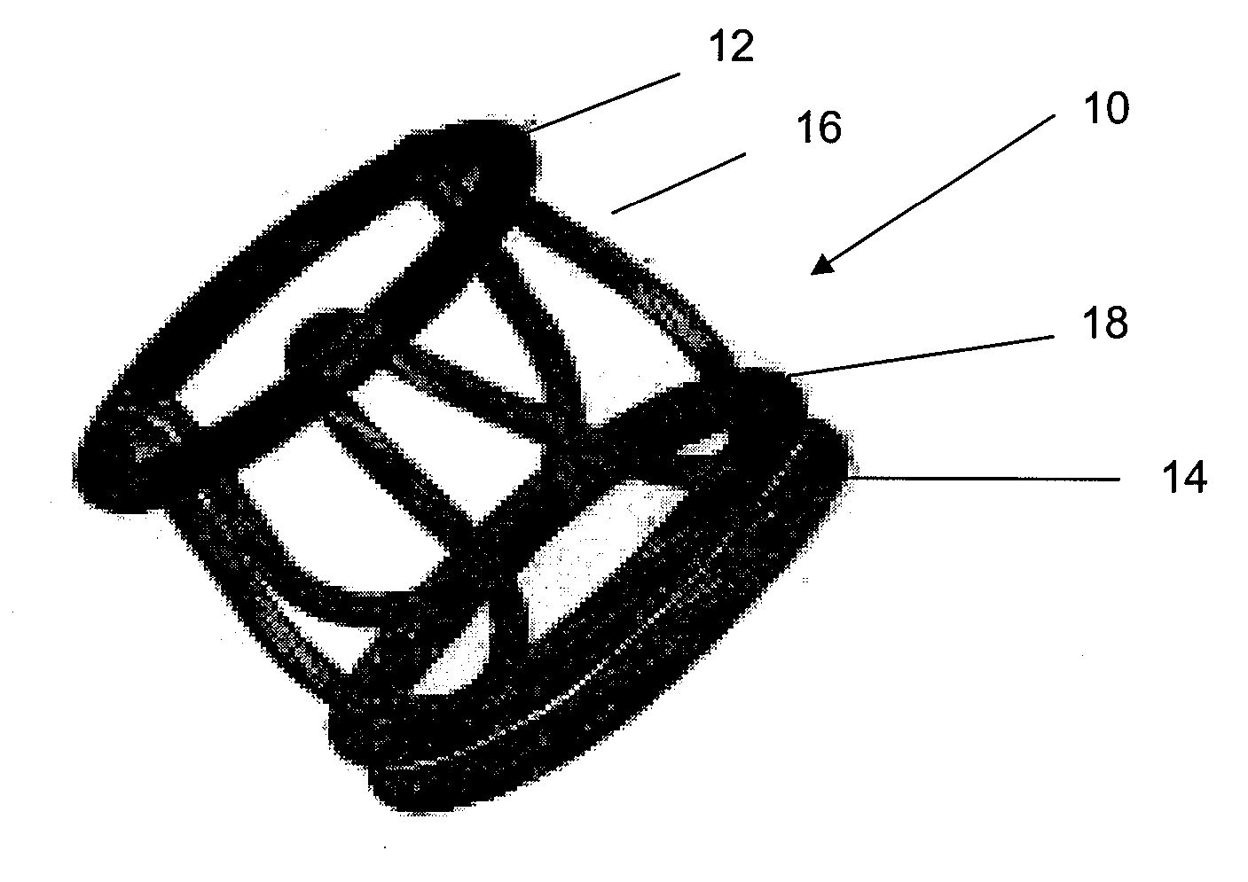
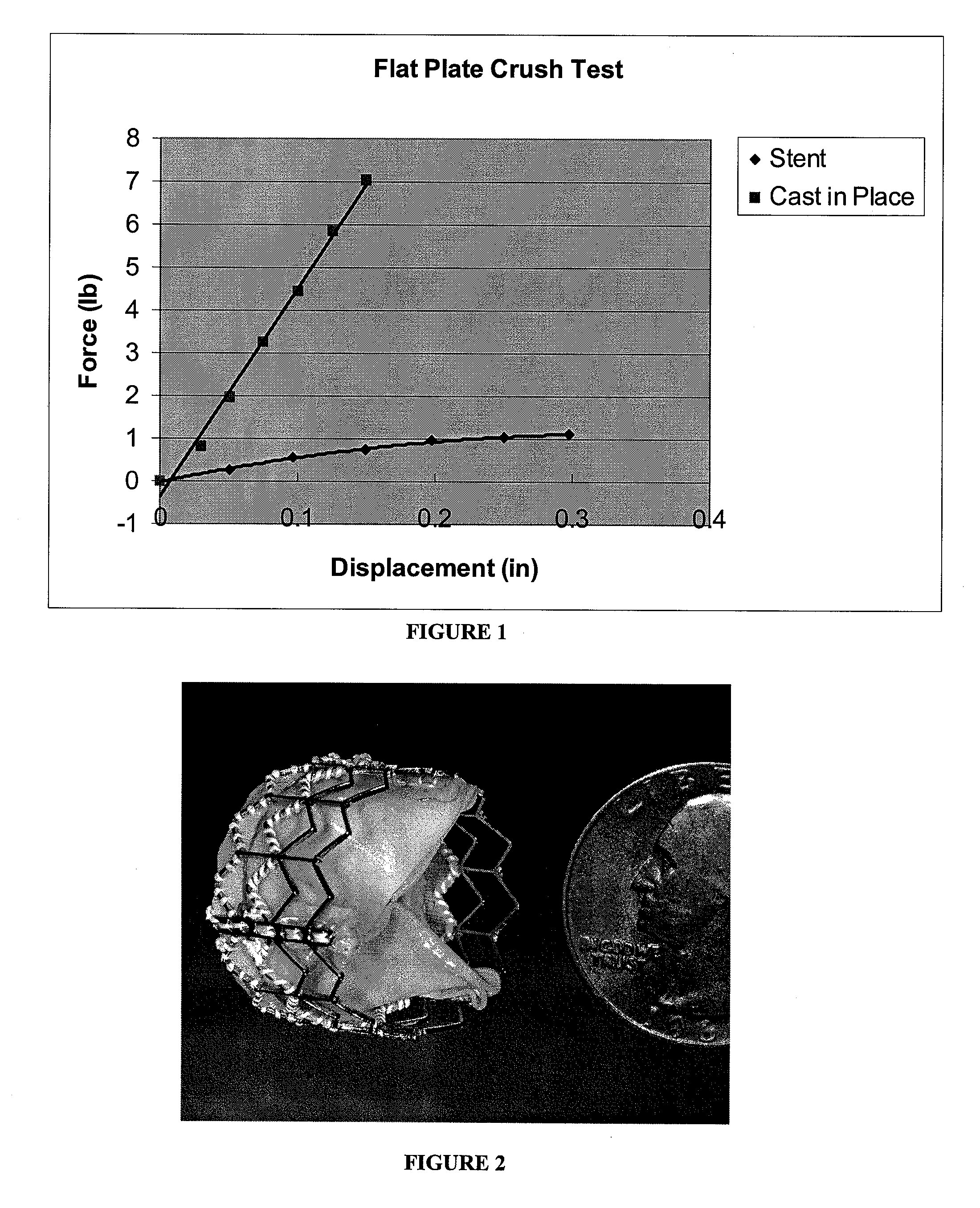
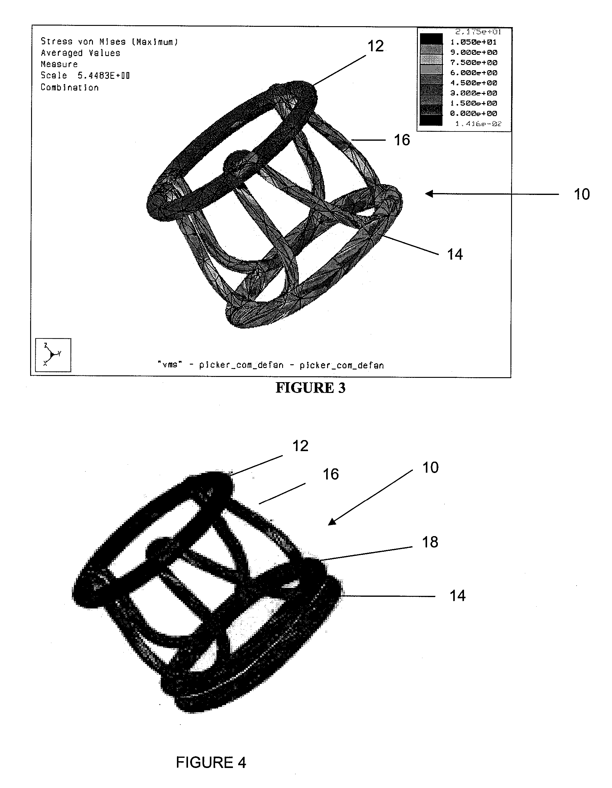
[0041] One current method for implanting a tissue valve percutaneously includes a balloon expandable or self-expanding stent with a tissue valve attached as described in Andersen U.S. Pat. No. 6,168,614. See FIG. 2. Another method to implant a tissue valve percutaneously is described in U.S. Pat. No. 5,554,185 (Block), the disclosure of which is incorporated in its entirety herein by reference. One key feature in any valve apparatus is the ability to withstand forces generated by the closure of the valve at the commissural supports. In surgical valves these are seen as posts or pillars rising from the base of the device. General construction often includes a metallic frame encompassed with silicone and wrapped with Dacron. This frame will withstand the cyclical loading seen under normal conditions of operation in a heart valve. Since surgical valves are installed under direct visualizat...


PUM


Abstract

Disclosed is a stentless transluminally implantable heart valve, having a formed in place support. The formed in place support exhibits superior crush resistance when compared to conventional balloon expandable or self expandable stent based valves.

Description

BACKGROUND OF THE INVENTION [0001] The malfunctioning of an aortic valve results in cardiac insufficiency and hence in a situation that is potentially fatal for the patient. For repair of such a defect, artificial aortic valves have been developed which are implanted as a substitute for the damaged valve in complex and risky open-heart surgery (sternotomy). The operation becomes particularly difficult when there is strong calcareous degeneration on the natural valve because painstaking attention must be paid during removal in order to ensure that calcification particles will not enter the blood circulation and cause there thromboses at other sites in the body. It is common to fasten the replacement valves—which are either mere engineering products or derived from porcine or other tissue valves—by suturing in the place of the removed valve. [0002] There are numerous approaches in the development of methods simplifying this complex procedure of aortic-valve replacement in terms of bot...

Claims


Application Information

Patent Timeline
IPC IPC(8): A61F2/24
CPCA61F2/2418A61F2/2469A61F2220/0066A61F2/24A61F2250/0003A61F2/2476A61F2/2409A61F2/2427A61F2/2415
Inventor LASHINSKI, RANDALL T.BISHOP, GORDON B.
Owner SPEYSIDE MEDICAL LLC
Why Eureka
Try Eureka