Implant for use between spiral vertebrae

a technology for implants and spiral vertebrae, which is applied in the direction of muscles, ligaments, medical science, etc., can solve the problems of inability to adjust to the individual conditions of patients, limitation of increasingly used minimal invasive surgery, etc., and achieve the effect of minimal invasive surgery

Inactive Publication Date: 2012-03-06
ULRIKH GMBKH & KO KG
View PDF11 Cites 23 Cited by
  • Summary
  • Abstract
  • Description
  • Claims
  • Application Information

AI Technical Summary

Benefits of technology

[0012]It is further particularly preferred within the scope of the invention, if the first implant part and the second implant part are formed as tubular sleeves, that a rotatable threaded ring having teeth is associated with the first implant part, which engages together with a ring thread into a thread arranged in the second implant part, and that a threaded bore is formed in the walls of the first implant for inserting a surgical instrument serving for rotating the threaded ring. The embodiment and the interaction of such first and second implant parts with a surgical instrument is generally known from EP 1 219 266 [U.S. Pat. No. 6,752,832], wherein the implant described therein, and not further explained herein, is suitable for the embodiment according to the invention utilizing the radially adjustable mounting bracket, thus overall enabling a minimally invasive procedure.
[0013]In order not to have to fix the mounting bracket as opposed to the implant part according to the analyses of the anatomic conditions ex situ before surgery, it is possible that tool fittings are formed on the screw head for rotating the retaining screw such that access is possible through the window on the screw head, and the retaining screw can also be further tightened in situ. To this end it is of advantage that the window and the threaded bore can be adjusted facing the same side.
[0014]It has proven advantageous, if seats are formed between the base plate and the end plate, enabling a primary fixation of location of the mounting bracket as opposed to the implant part before the final fixation of location is carried out by means of tightening the retaining screw. To this end, the seats are advantageously formed by ridges extending transverse to the radial adjustment direction of the guide rail.

Problems solved by technology

One disadvantage of this known implant, however, is that it is subject to limitation in increasingly used minimal invasive surgery, because in order to change the length of the implant the center implant must be adjusted as opposed to the end implant part by attaching to it a tool that moves in a circular arc, and adjustment to the individual conditions of the patient is not possible due to the arrangement of the mounting bracket on the outer circumference of the end implant part.

Method used


Image

  • Implant for use between spiral vertebrae
  • Implant for use between spiral vertebrae
  • Implant for use between spiral vertebrae

Examples


Embodiment Construction

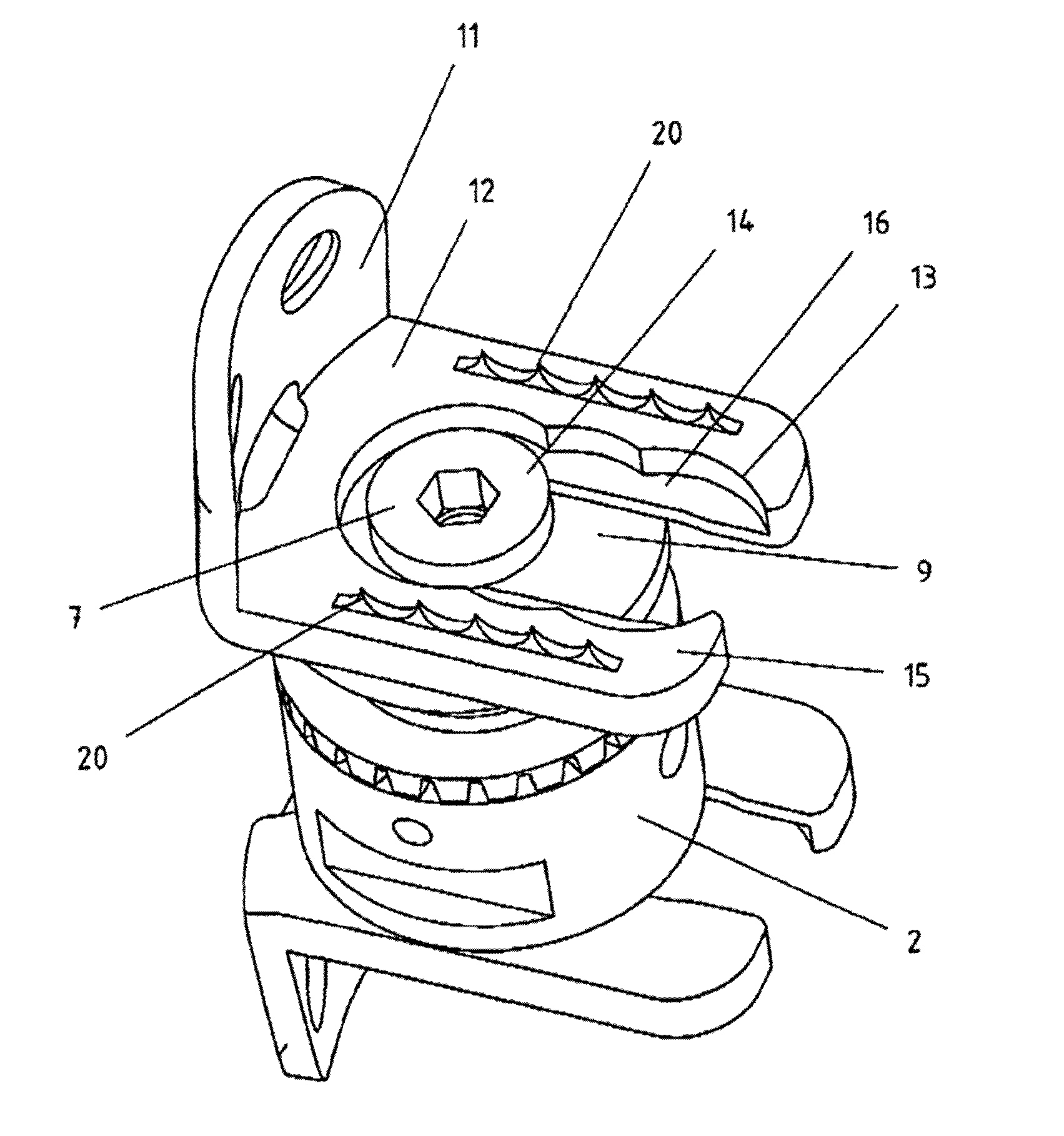
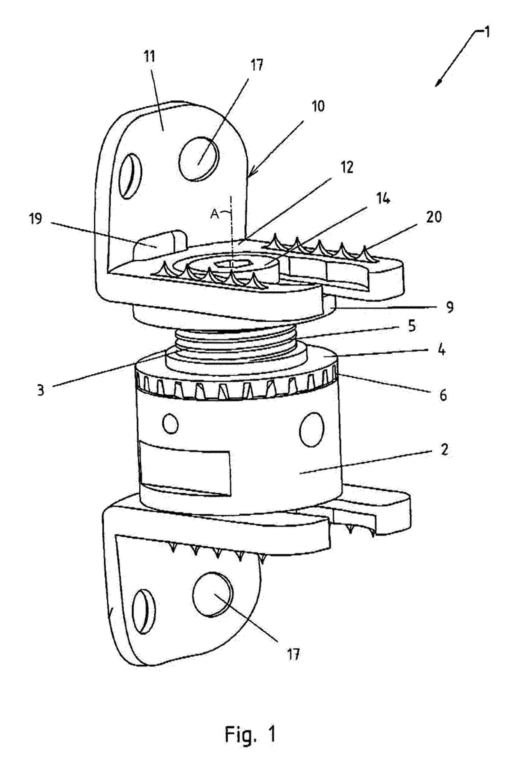
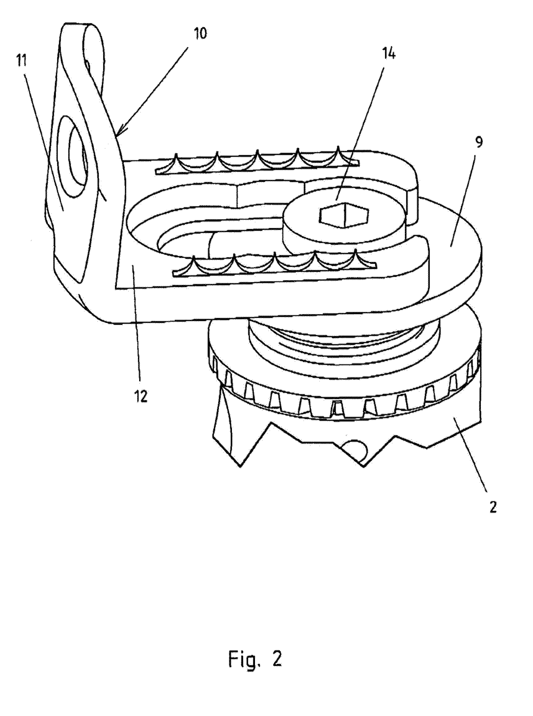
[0023]FIG. 1 shows an implant 1 for use between vertebrae 8 of the spine as placeholders for vertebrae or vertebral parts removed from the spine. This implant 1 consists of a first implant part 2 and a second implant part 3 that can be moved relative to each other in the direction of their coaxial longitudinal axes for changing the length of the implant 1. This adjustability is achieved in that the first implant part 2 and the second implant part 3 are formed as tubular sleeves, the first implant part 2 surrounding the second implant part 3 and having a rotatable threaded ring 4 carried on the first implant part 2 and having an annular screwthread on its inner edge by means of which it engages into a screwthread 5 of the second implant part 3. The threaded ring 4 is equipped with teeth 6, particularly pinion teeth, on its is outer surface such that the change of length can be achieved for distraction of the vertebrae 8 by rotation of the threaded ring 4 by means of a surgical instru...


PUM


Abstract

The invention relates to an implant for use between the vertebrae (8) of the spine as a placeholder for vertebrae or vertebrae parts removed from the spine, having a first implant part (2) and a second implant part (3), which can be adjusted against each other in the direction of the coaxial longitudinal axis thereof for changing the length of the implant (1), and having at least one mounting bracket (10) that can be attached to one of the implant parts (2 and 3), and which faces the adjacent vertebra, and partially overlaps the same. The mounting bracket (10) is formed by a vertebra attachment plate (11) and by a base plate (12) comprising a guide rail (13), protruding from the vertebra attachment plate, and serving for the radial adjustment of the mounting bracket (11) as opposed to the one implant part (2 and 3), is wherein a means is associated with the one implant part (2 and 3) for the radial fixation of the base plate (12).

Description

FIELD OF THE INVENTION[0001]The invention relates to an implant for implantation between vertebrae of the spine as a placeholder for vertebrae or vertebral parts removed from the spine, having a first implant part and a second implant part that can be moved relative to each other in the direction of their coaxial longitudinal axis for changing the length of the implant and having at least one mounting bracket that can be attached to one of the implant parts and is that directed toward the adjacent vertebra, at least partially overlapping same.BACKGROUND OF THE INVENTION[0002]Such an implant is known from EP 0 950 388 [U.S. Pat. No. 6,190,413]. This implant is comprised of a total of three implant is parts; two end permanent parts installed on the adjacent vertebra, and one center implant part positioned between them, which are connected to each other via screwthreads. Holes are formed in the end implant parts serving primarily for enabling access to the interior of the implant parts...

Claims


Application Information

Patent Timeline
Patent Type & Authority Patents(United States)
IPC IPC(8): A61F2/44
CPCA61F2/442A61F2002/30115A61F2002/30233A61F2002/30406A61F2002/30433A61F2002/30434A61F2002/30495A61F2002/30509A61F2002/3055A61F2002/30553A61F2002/30578A61F2002/30579A61F2002/30598A61F2002/30604A61F2002/30841A61F2220/0025A61F2220/0041A61F2230/0006A61F2230/0069A61F2250/0007A61F2250/0008A61F2002/30507A61F2002/30594
Inventor KAST, ERICH
Owner ULRIKH GMBKH & KO KG
Why Eureka
Try Eureka