Wiper blade

Active Publication Date: 2008-11-27
THE KOREA DEV BANK
View PDF18 Cites 97 Cited by
  • Summary
  • Abstract
  • Description
  • Claims
  • Application Information

AI Technical Summary

Benefits of technology

[0013]In one embodiment, a wiper blade is provided that has improved coupling structure between respective components of

Problems solved by technology

However, since the plural link members 3, 5 and 7 of the conventional wiper blade are pivotably coupled to one another as described above, there are disadvantages such as noise generation at coupled positions between the link members, corrosion resu

Method used


Image

  • Wiper blade
  • Wiper blade
  • Wiper blade

Examples


Embodiment Construction

[0032]Exemplary embodiments of the present invention will be described in detail with reference to the accompanying drawings hereinafter.

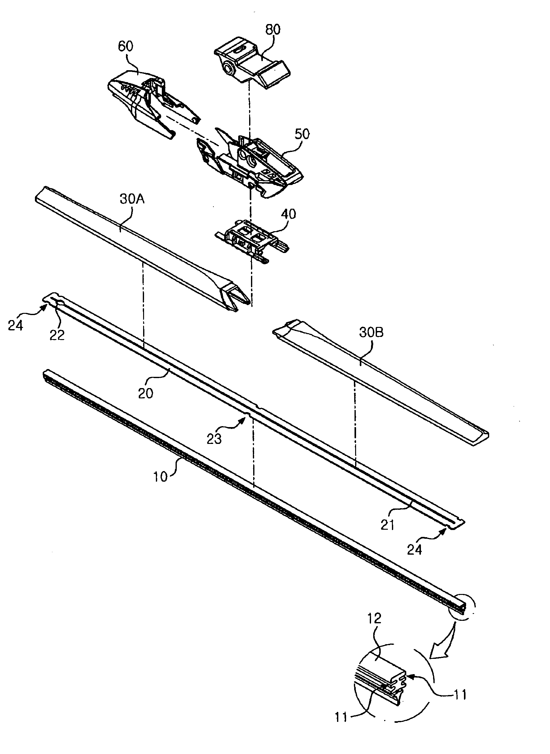
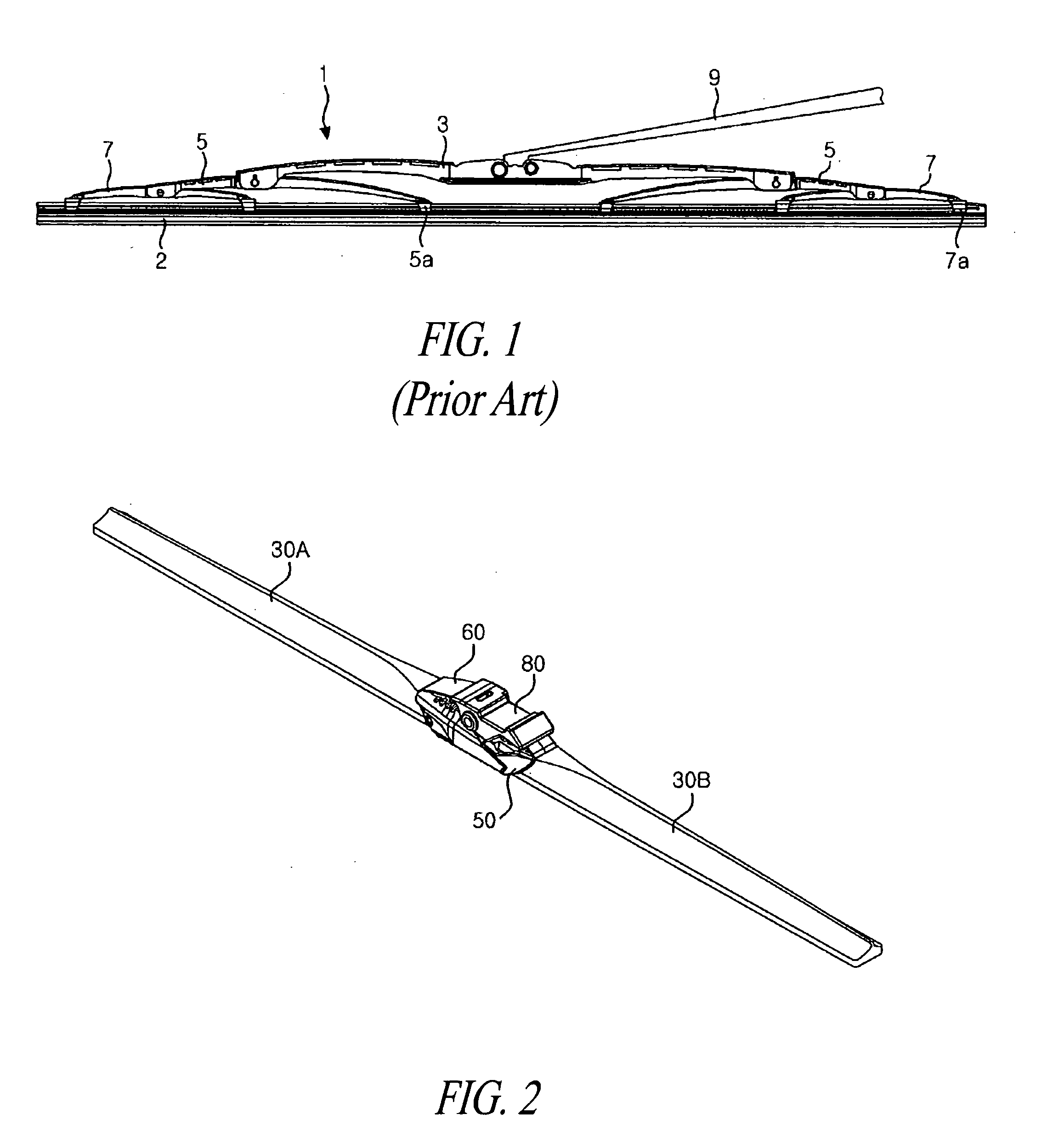
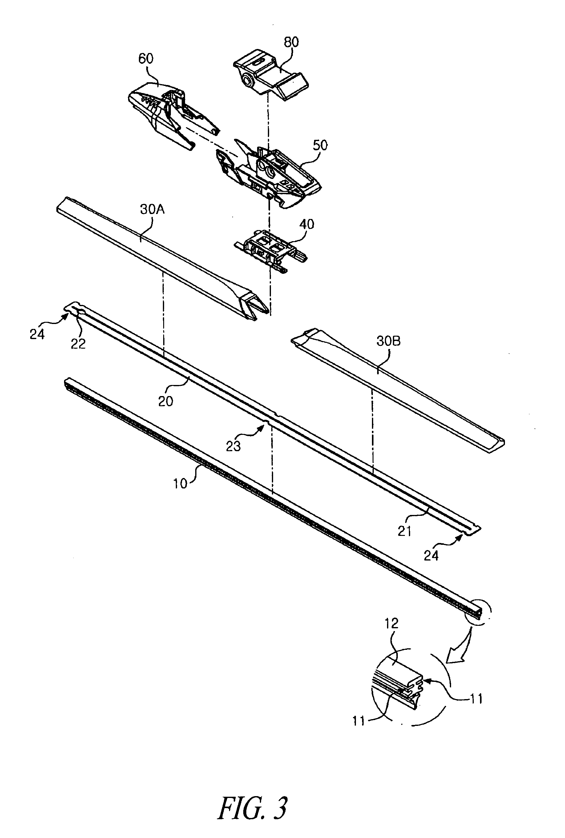
[0033]FIG. 2 is a perspective view of a wiper blade according to one embodiment, and FIG. 3 is an exploded perspective view of the wiper blade of FIG. 2.

[0034]Referring to FIGS. 2 and 3, a wiper blade according to one embodiment includes a wiper strip 10 contacting a glass surface of a vehicle to wipe the glass surface while pivoting across the glass surface, a frame 20 coupled to the wiper strip 10, and a bracket 50 disposed at a center of the frame 20 to couple the wiper blade to a wiper arm (not shown).

[0035]According to one embodiment, the wiper blade may further include a joint 40 disposed between the frame 20 and the bracket 50 to secure the bracket 50 and the frame 20, and a cover 60 slidably and pivotably provided to the bracket 50.

[0036]Left and right spoilers 30A and 30B may be respectively coupled to right and left sides of the frame 20 ...


PUM


Abstract

Disclosed herein is a wiper blade coupled to or configured to be coupled to a wiper arm of a vehicle to wipe a glass surface of a windshield. The wiper blade includes a wiper strip configured to contact the glass surface, a frame coupled to the wiper strip, a bracket disposed at a center of the frame and joined to the wiper arm, and a joint disposed between the frame and the bracket to secure the bracket to the frame.

Description


Claims


Application Information

Patent Timeline
Owner THE KOREA DEV BANK
Why Eureka
Try Eureka