Apparatus for clamping disk of spindle motor and spindle motor having the same

Inactive Publication Date: 2010-09-23
LG INNOTEK CO LTD
View PDF5 Cites 9 Cited by
  • Summary
  • Abstract
  • Description
  • Claims
  • Application Information

AI Technical Summary

Benefits of technology

[0007]The present disclosure is to provide an apparatus for clamping disk (hereinafter called a disk clamping apparatus) of a spindl

Problems solved by technology

As a result, the arm suffers from a disadvantage in that a coupling force between the arm and the disk

Method used


Image

  • Apparatus for clamping disk of spindle motor and spindle motor having the same
  • Apparatus for clamping disk of spindle motor and spindle motor having the same
  • Apparatus for clamping disk of spindle motor and spindle motor having the same

Examples


Example

[0016]An apparatus for clamping disk of spindle motor and a spindle motor having the same will be described in detail with reference to the accompanying drawings.

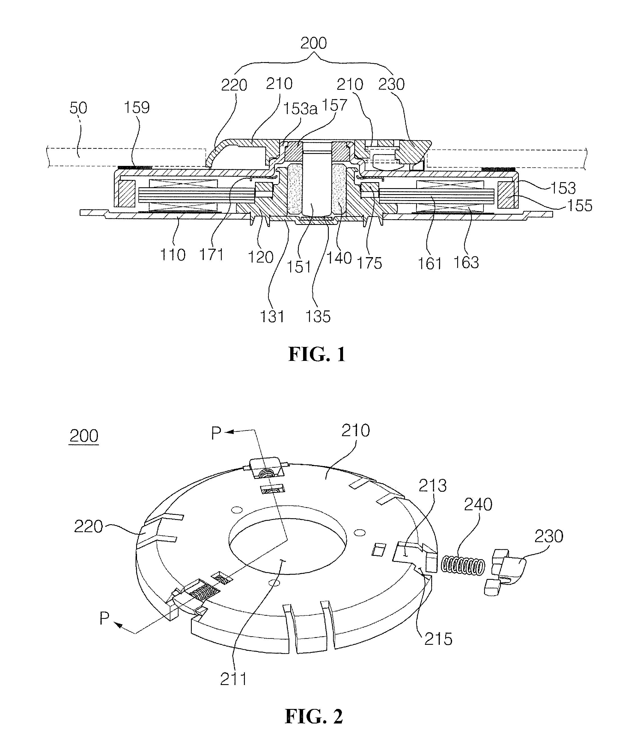
[0017]FIG. 1 is a cross-sectional view of a disk clamping apparatus and a spindle motor having the same according to an exemplary embodiment of the present invention.

[0018]Referring to FIG. 1, a bearing housing 120 is perpendicularly arranged on the base 110.

[0019]In designating a direction and a surface of constituent parts, a direction and a surface facing an upper vertical side of the base 110 are respectively called “an upper side” and “an upper surface”, while a direction and a surface facing a bottom vertical side of the base 110 are respectively called “a bottom side” and “a bottom surface”.

[0020]The cylindrical bearing housing 120 with upper and bottom surfaces opened and the bottom surface being coupled to the base 110 is provided.

[0021]The bearing housing 120 is coupled at a bottom surface to a thrust stopper 131,...


PUM


Abstract

A disk clamping apparatus of a spindle motor and a spindle motor having the same are disclosed, wherein the apparatus includes a case inserted into an inner periphery of a disk for integrally rotating with a rotation shaft coupled with a rotor yoke, a plurality of claws each formed at a predetermined gap in the case, an arm mounted between the claws in the case and having a body with a slanted surface and slantedly formed at an upper surface of the disk, guide rails each mounted at both lateral surfaces of the body and a disengagement prevention rails each mounted at each guide rail and curvedly formed at the bottom surface for contacting the rotor yoke, and an elastic member elastically supporting the body by being interposed between the body and the case.

Description

CROSS-REFERENCE TO RELATED APPLICATION[0001]This application claims the benefit under 35 U.S.C. §119 of Korean Application Number 10-2009-0024433, filed Mar. 23, 2009, which is hereby incorporated by reference in its entirety.BACKGROUND[0002]The present disclosure relates to an apparatus for clamping disk of spindle motor and a spindle motor having the same.[0003]In general, a spindle motor performs the function of rotating a disk at a high speed to enable an optical pickup which linearly reciprocates in an optical disk drive (ODD) to read data recorded on the disk.[0004]A spindle motor includes a stator, a rotation shaft rotating relative to the stator, a rotor fixed to the rotation shaft and including a rotor yoke, and a disk clamping apparatus rotating with the rotation shaft and fixing the disk.[0005]The disk clamping apparatus fixing the disk includes a disk-shaped case, a plurality of claws formed at a lateral surface of the case to contact an inner periphery of the disk and t...

Claims


Application Information

Patent Timeline
IPC IPC(8): G11B19/20H02K7/14
CPCG11B17/0282H02K5/16H02K29/00
Inventor YOON, HO EOP
Owner LG INNOTEK CO LTD
Why Eureka
Try Eureka