Resistance box with convenience in air guiding and heat dissipating

A resistance box and air guide technology, applied in the direction of resistors, resistor parts, resistor shells/packaging shells/potting, etc., can solve the problems of fan cost increase, large power, high cost, etc., to avoid excessive temperature concentration High, reduce the loss of air volume, improve the effect of heat dissipation

Active Publication Date: 2017-08-11
GUANGDONG FULLDE ELECTRONICS +1
View PDF11 Cites 0 Cited by
  • Summary
  • Abstract
  • Description
  • Claims
  • Application Information

AI Technical Summary

Problems solved by technology

However, the cost of the fan increases with the increase of the fan power, and the high-power fan consumes a large amount of electric energy
[0003] The current structure of the resistance box is as follows figure 1 As shown, the box body 1 and the resistance element 2 placed in the box body 1 are included, and the box body 1 is provided with a fan 3. The inventors found that, for the consideration of installation, maintenance and electrical performance, the resistance element 2 and the box body 1 There is a large distance around the channel between the inner walls. The resistance element 2 is located in the middle of the box body 1. Since the air volume always flows to the place with low wind resistance, there is a large air volume around the channel, and the resistance element 2 flowing through the middle The air volume of element 2 is the smallest, which affects the heat dissipation effect inside the resistance box. In order to achieve a better heat dissipation effect, a fan with a higher power is selected, and the greater the air volume lost, the higher the cost caused by it

Method used


Image

  • Resistance box with convenience in air guiding and heat dissipating
  • Resistance box with convenience in air guiding and heat dissipating

Examples


Embodiment Construction

[0022] The present invention will be described in detail below in conjunction with specific embodiments and accompanying drawings.

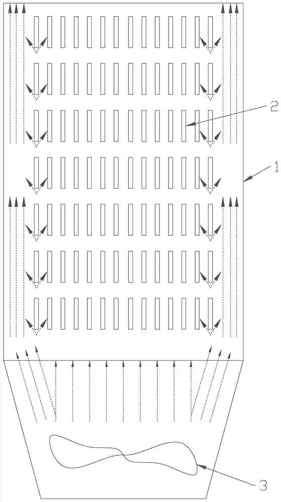
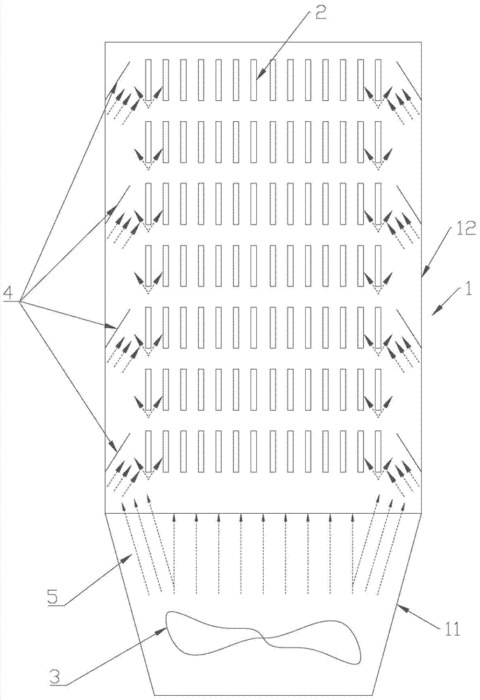
[0023] A kind of resistance box that is convenient to conduct wind and dissipate heat in this embodiment, such as figure 2 As shown, it includes a box body 1 that is hollow to form an inner cavity. The box body 1 includes a continuous bearing section 11 and an accommodating section 12. The accommodating section 12 is used to place the resistance element 2. The upper end of the accommodating section 12 is open for ventilation. There is a certain gap between the elements 2, and the inside of the carrying section 11 is provided with a fan 3 for blowing towards the accommodating section 12, and the fluid blown out by the fan 3 is as figure 2 Indicated by the dotted arrow 5. The cross section of the accommodating section 12 is quadrilateral, and each inner wall of the accommodating section 12 is provided with a plurality of air guides 4, and the pl...


PUM


Abstract

The invention discloses a resistance box with convenience in air guiding and heat dissipating. The resistance box comprises a hollow box body with an inner cavity; the box body comprises continuous bearing section and accommodating section; the accommodating section is used for placing resistance elements; a fan which blows air towards the accommodating section is arranged in the bearing section; air guiding parts are fixed on the inner wall of the accommodating section; and the air guiding parts are inclined towards the inner cavity of the box body. By virtue of the air guiding parts in the box body, (1) air flow loss is lowered, air flow which flows through the resistance elements is higher in amount, and more heat can be taken away under the effect of the fan of the same powder, so that partial overhigh temperature of the box body can be avoided and the heat dissipation effect is improved; (2) turbulent current is formed between the resistance elements, so that heat generated by the resistance elements can be taken away more easily; and (3) the air guiding parts are directly impacted by the air flow, and the heat on the side wall of the box body can be taken away by the air guiding parts, so that the air guiding parts also can have a thermal insulation effect, thereby lowering the temperature of the side wall of the box body, and reducing heat dissipation from the side surface of the box body.

Description

technical field [0001] The invention relates to the technical field of resistance boxes, in particular to a resistance box which is convenient for wind conduction and heat dissipation. Background technique [0002] High-power resistors are widely used in energy consumption control systems powered by variable frequency motors, industrial motor start-up, speed regulation, and braking control systems, as well as simulated loads of various industrial electrical appliances and neutral point grounding resistance in power distribution systems. . A box is generally installed on the outside of a high-power resistor, which is usually called a "resistance box" or "resistance cabinet", and its function is to protect the resistor from external influences during use, especially to prevent rain and moisture, or Prevent water droplets formed by condensation of humid air on the resistors, or prevent flying animals from entering the interior of the cabinet. The power of the power consumptio...

Claims


Application Information

Patent Timeline
Patent Type & Authority Applications(China)
IPC IPC(8): H01C1/02H01C1/082
CPCH01C1/02H01C1/082
Inventor 黎志盈许丰梁锦桥吴彬阮云鹏
Owner GUANGDONG FULLDE ELECTRONICS
Why Eureka
Try Eureka