an automatic stamping machine

A punching machine, automatic technology, applied in the directions of feeding devices, manufacturing tools, positioning devices, etc., can solve the problems of dangerous manual operation, low production efficiency, waste of manpower, etc., to improve stamping accuracy, high production efficiency, and safety. high effect

Active Publication Date: 2019-02-01
GUANGZHOU HUADU ZHIDA STAINLESS STEEL PROD +1
View PDF7 Cites 0 Cited by
  • Summary
  • Abstract
  • Description
  • Claims
  • Application Information

AI Technical Summary

Problems solved by technology

[0002] Stamping machines are used to mass-produce mechanical structures or components. They are common production equipment. Some equipment parts need to be stamped multiple times. Each stamping process requires manual feeding and stripping and the processed parts are stamped from one Transferring the machine to another stamping machine, the steps are cumbersome, resulting in low production efficiency and waste of manpower. If the operator makes mistakes in the stamping process, it may cause damage to the processed parts, and manual operation has certain dangers.

Method used


Image

  • an automatic stamping machine
  • an automatic stamping machine
  • an automatic stamping machine

Examples


Embodiment 1

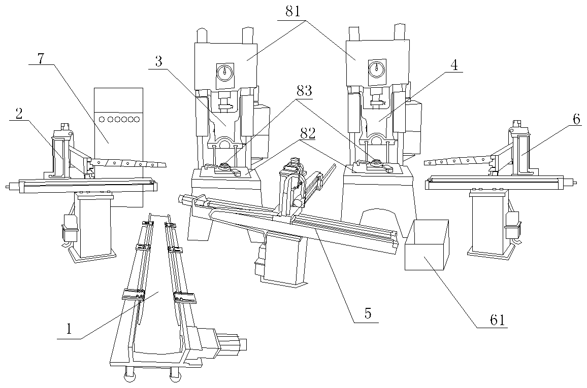
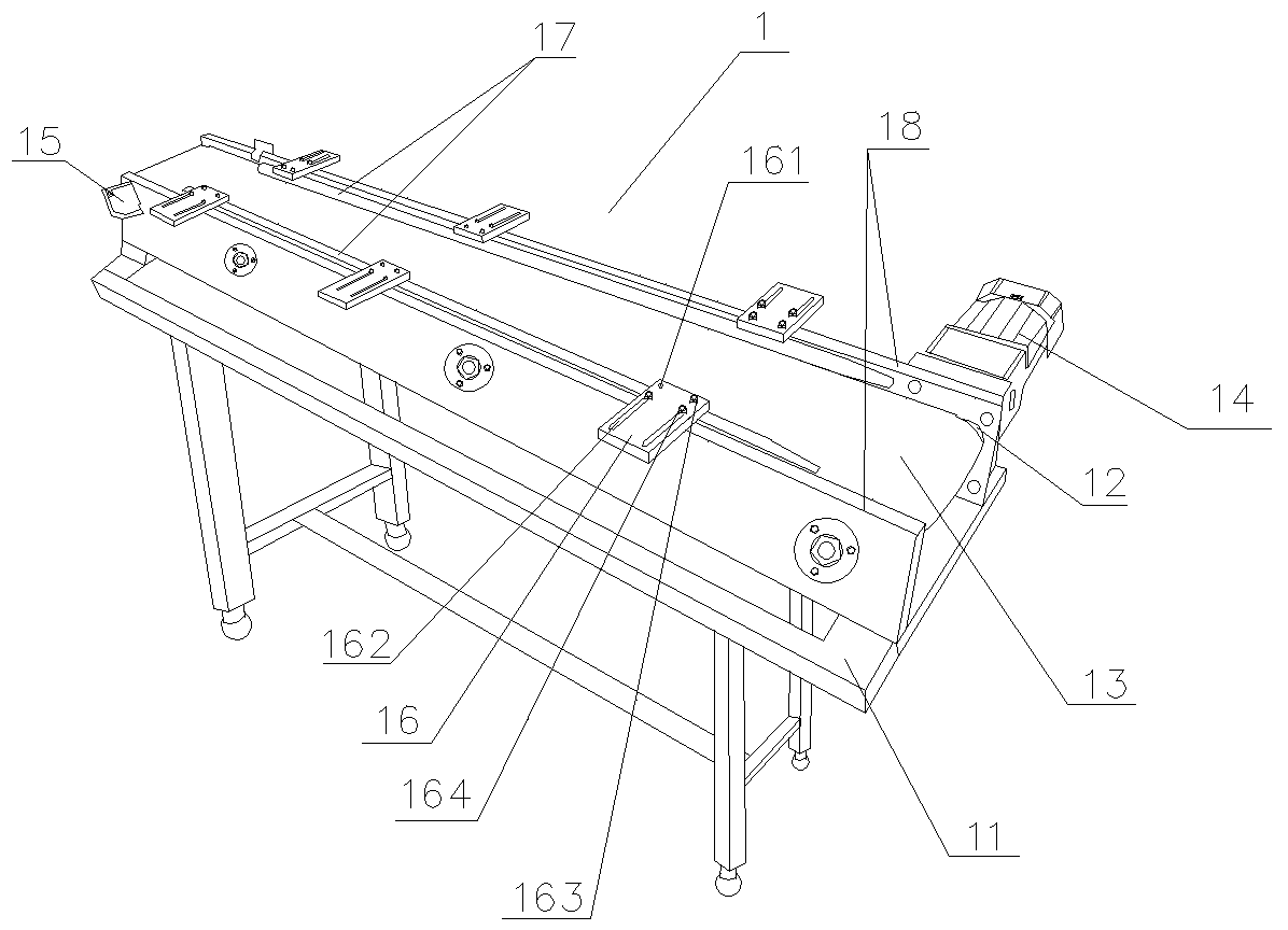
[0022] Embodiment one: if Figure 1-3 Shown is a schematic structural diagram of an embodiment of an automatic stamping machine provided by the present invention, including at least one stamping device, and also includes an automatic feeding device 1, at least one three-axis feeding manipulator, three-axis reclaiming manipulator 6 and an automatic control system 7, The three-axis feeding manipulator is located on the left side of the stamping device, the three-axis retrieving manipulator 6 is located on the right side of the stamping device, the automatic feeding device 1 is located in front of the three-axis feeding manipulator, and the three-axis reclaiming manipulator 6 is provided with a storage basket 61, automatic control system 7 Control the automatic feeding device 1, the three-axis feeding manipulator, the stamping device and the three-axis reclaiming manipulator 6. Automatically load, take out, stamp and unload in an orderly and coherent manner. The three-axis feedin...

Embodiment 2

[0025] Embodiment two: if Figure 4-5 As shown, the punching device in Embodiment 1 includes a first punching device 3 and a second punching device 4, and the three-axis feeding manipulator includes the first three-axis feeding manipulator 2 and the second three-axis feeding manipulator 5, the first punching device 3 and the second three-axis feeding manipulator. The second stamping device 4 is arranged side by side, the first three-axis feeding manipulator 2 is located on the left side of the first stamping device 3, the three-axis retrieving manipulator 6 is located on the right side of the second stamping device 4, and the second three-axis feeding manipulator 5 is located on the first stamping In front of the device 3 and the second stamping device 4, the automatic feeding device 1 is located on the left side of the second three-axis feeding manipulator 5. The workpiece punched by the first punching device is a workpiece with a rectangular hole 19 , and the second punching...

Embodiment 3

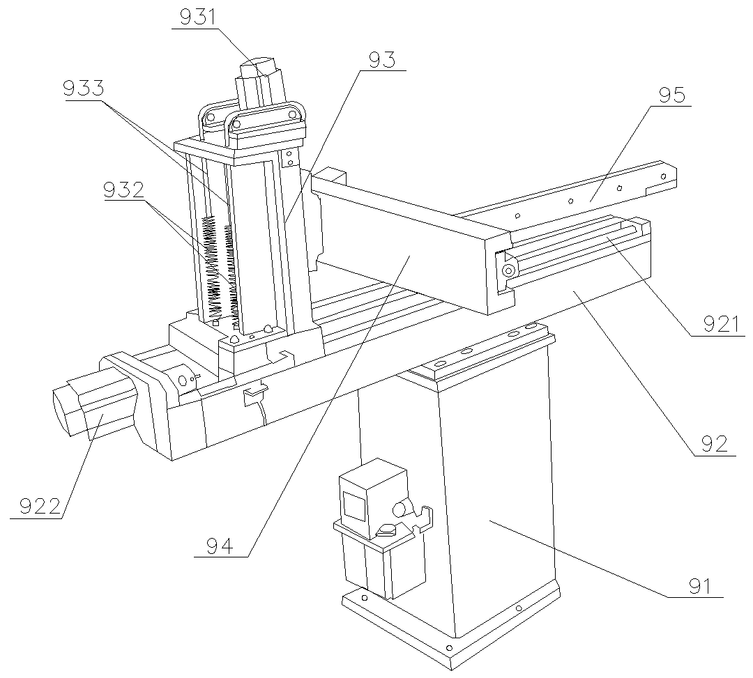
[0026] Embodiment three: the lifting chute 93 in embodiment one also includes a longitudinal chute stabilizing device, and the longitudinal chute stabilizing device includes two springs 932 arranged vertically and parallel to each other, and one end of the spring 932 is connected to the left side of the lifting chute 93. The bottom is connected, and the other end of spring 932 is connected with chain 933, and chain 933 passes the sprocket wheel that is provided with on the top of lifting chute 93 from the left side of lifting chute 93 and then winds to the right side of lifting chute 93 and with the longitudinal sliding Groove 94 connection.


PUM


Abstract

The invention discloses an automatic punch. The automatic punch comprises at least one punching device, and further comprises an automatic feeding device, at least one three-shaft feeding manipulator, a three-shaft taking manipulator and an automatic control system; the three-shaft feeding manipulator is positioned on the left side of the punching device; the three-shaft taking manipulator is positioned on the right side of the punching device; the automatic feeding device is positioned in front of the three-shaft feeding manipulator; a storage basket is arranged under the three-shaft taking manipulator; and the automatic control system controls the automatic feeding device, the three-shaft feeding manipulator, the punching device and the three-shaft taking manipulator to automatically and continuous operate loading, taking, punching and unloading in sequence. The automatic punch is high in production efficiency, saves the manpower, improves the punching precision, and is high in safety.

Description

technical field [0001] The invention belongs to the technical field of mechanical manufacturing, in particular to an automatic stamping machine. Background technique [0002] Stamping machines are used to mass-produce mechanical structures or components. They are common production equipment. Some equipment parts need to be stamped multiple times. Each stamping process requires manual feeding and stripping and the processed parts are stamped from one If the operator makes a mistake in the stamping process, it may cause damage to the processed parts, and manual operation has certain risks. Contents of the invention [0003] The object of the present invention is to solve the above-mentioned problems and deficiencies, and provide an automatic punching machine with high production efficiency, saving manpower, improving punching precision, and high safety. [0004] The technical solution of the present invention is realized in the following way: an automatic punching machine i...

Claims


Application Information

Patent Timeline
Patent Type & Authority Patents(China)
IPC IPC(8): B21D43/10B21D43/12B21D43/18B21D43/20B21D35/00
CPCB21D35/002B21D43/105B21D43/12B21D43/18B21D43/20
Inventor 侯旭敏王旭明
Owner GUANGZHOU HUADU ZHIDA STAINLESS STEEL PROD
Why Eureka
Try Eureka