Generator set part placing tool

A technology for generator sets and parts, applied in the field of generator set parts placement tooling, can solve the problems of reducing the service life of parts and high precision requirements of generator set parts, and achieves the effect of prolonging service life, convenient installation and increasing placement space

Active Publication Date: 2017-09-12
HEFEI CALSIION ELECTRIC POWER SYST
View PDF5 Cites 1 Cited by
  • Summary
  • Abstract
  • Description
  • Claims
  • Application Information

AI Technical Summary

Problems solved by technology

[0002] A generator set is a complete set of mechanical equipment that converts other forms of energy into electrical energy. It is composed of a power system, a control system, a noise reduction system, a shock absorption system, and an exhaust system. It is driven by a water turbine, steam turbine, diesel engine or other power machinery. , air flow, fuel combustion or nuclear fission, the energy generated is converted into mechanical energy and transmitted to the generator, and then converted into electrical energy by the generator, which is output to the electrical equipment for use. There are diesel generator sets, gas generator sets, gasoline generator sets, and wind power generators. Units, solar generators, hydroelectric generators, coal-fired generators, etc., are assembled from different parts for different generators. Traditional generator parts are placed together or placed directly on the shelf In general, the commonly used racks are directly fixed on the base, which requires high precision for the parts of the generator set. During use and placement, collisions may easily cause damage to the parts or reduce the service life of the parts.

Method used


Image

  • Generator set part placing tool
  • Generator set part placing tool
  • Generator set part placing tool

Examples


Embodiment Construction

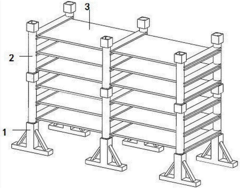
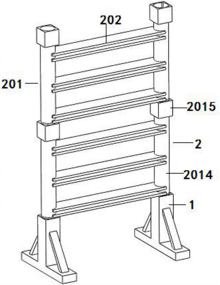
[0027] A tool for placing generator set parts, such as figure 1 , figure 2 and image 3 As shown, it includes several sets of relative fixing devices and a storage board 3 fixed between two adjacent fixing devices. The fixing device includes two opposite base frames 1 and several sequentially connected and fixed elastic supports. Frame 2, two pedestals 1 are installed and fixed vertically upwards with several sequentially connected and fixed elastic support frames 2, and several storage plates 3 are installed on the elastic support frames 2;

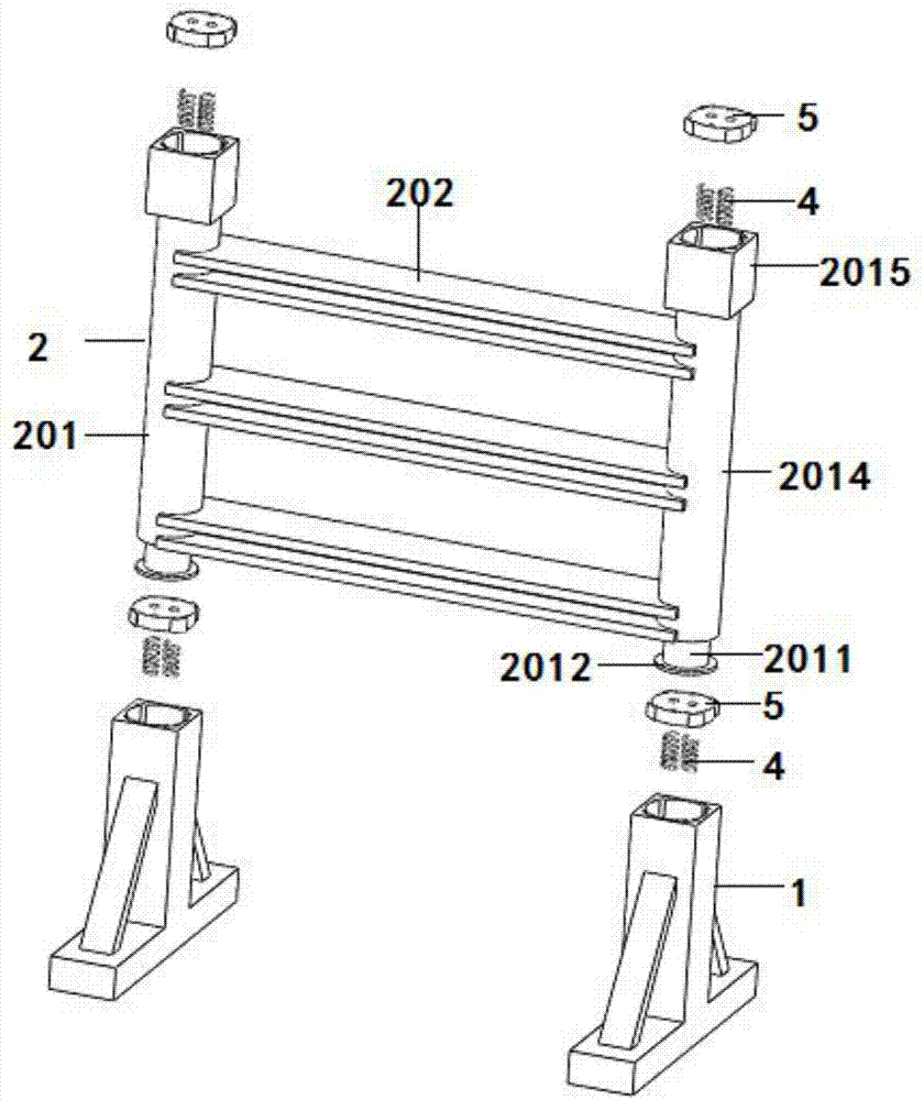
[0028] Such as Figure 4 As shown, the base frame 1 includes a fixed rod 101, the surface of the fixed rod 101 is vertically fixed with a support rod 101, and the outer surface of the opposite side wall of the support rod 101 is connected with the surface of the fixed rod 101 to be fixed with reinforcing ribs 103. Elastic support frame 2 is installed and fixed on the top of 102;

[0029] The top surface of the support rod 101 is pro...


PUM


Abstract

The invention discloses a generator set part placing tool. The generator set part placing tool comprises multiple sets of fixing devices oppositely arranged, and object placing plates fixed between two adjacent fixing devices; the fixing devices comprise two base frames oppositely arranged, and multiple elastic support frames fixedly connected in sequence; the multiple elastic support frames fixedly connected in sequence are fixedly mounted on the two base frames in the vertical direction; and the multiple object placing plates are mounted on the elastic support frames. The tool is provided with the base frames and the multiple elastic support frames; the object placing plates are connected between the elastic support frames; springs are arranged at the connected parts of the base frames and the elastic support frames; through the damping effect of the springs, the shortening of the service life of parts due to collision of the parts in taking and placement can be prevented, and the service life of the object placing plates is prolonged; and meanwhile, the number of the elastic support frames in the vertical direction is increased, and the numbers of the fixing devices and the object placing plates in the horizontal direction are increased, so that the placing space of the placing tool can be increased.

Description

technical field [0001] The invention belongs to the field of generating set equipment, and relates to a tool for placing components of a generating set. Background technique [0002] A generator set is a complete set of mechanical equipment that converts other forms of energy into electrical energy. It is composed of a power system, a control system, a noise reduction system, a shock absorption system, and an exhaust system. It is driven by a water turbine, steam turbine, diesel engine or other power machinery. , air flow, fuel combustion or nuclear fission, the energy generated is converted into mechanical energy and transmitted to the generator, and then converted into electrical energy by the generator, which is output to the electrical equipment for use. There are diesel generator sets, gas generator sets, gasoline generator sets, and wind power generators. Units, solar generators, hydroelectric generators, coal-fired generators, etc., are assembled from different parts ...

Claims


Application Information

Patent Timeline
Patent Type & Authority Applications(China)
IPC IPC(8): B25H3/00
CPCB25H3/00
Inventor 杜永辉
Owner HEFEI CALSIION ELECTRIC POWER SYST
Why Eureka
Try Eureka