Integrated internal-expanding type mechanical-locking hydraulic supporting leg and operating method thereof

A technology of mechanical locking and hydraulic outriggers, applied in mechanical equipment, transportation and packaging, fluid pressure actuating devices, etc., can solve problems such as many oil leakage points, narrow installation space, and complicated pipeline layout.

Pending Publication Date: 2017-11-17
SOUTH CHINA UNIV OF TECH +1
View PDF5 Cites 2 Cited by
  • Summary
  • Abstract
  • Description
  • Claims
  • Application Information

AI Technical Summary

Problems solved by technology

These three oil circuits need to be connected to the on-board hydraulic power system through three external oil pipes on the hydraulic outrigger. Therefore, compared with the hydraulic outriggers of ordinary engineering vehicles, the number of oil ports of the internal expansion mechanical locking hydraulic outriggers is increased. In the process, there are disadvantages such as the vehicle hydraulic system needs to be modified, the installation space is small, the pipeline layout is complicated, and there are many oil leakage points.

Method used


Image

  • Integrated internal-expanding type mechanical-locking hydraulic supporting leg and operating method thereof
  • Integrated internal-expanding type mechanical-locking hydraulic supporting leg and operating method thereof
  • Integrated internal-expanding type mechanical-locking hydraulic supporting leg and operating method thereof

Examples


Embodiment

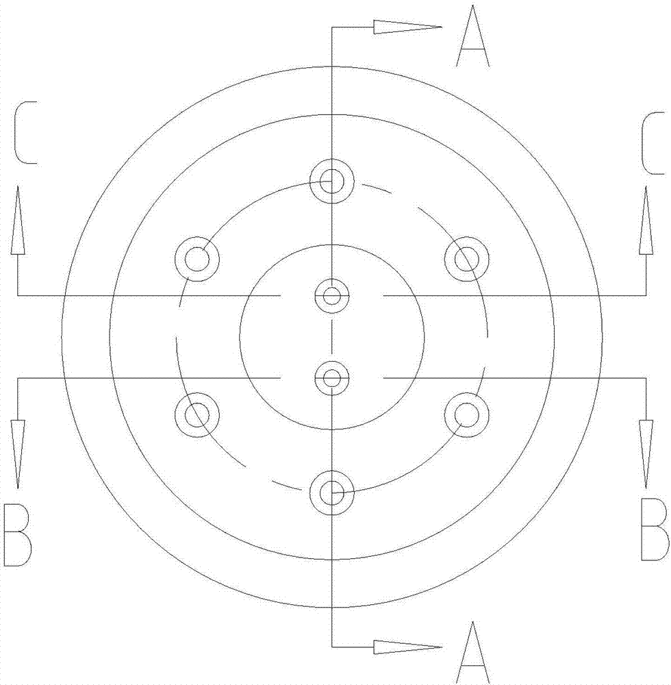
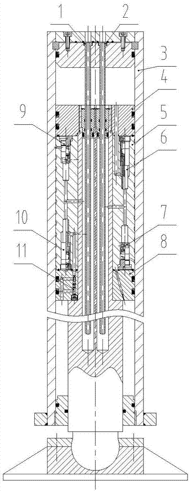
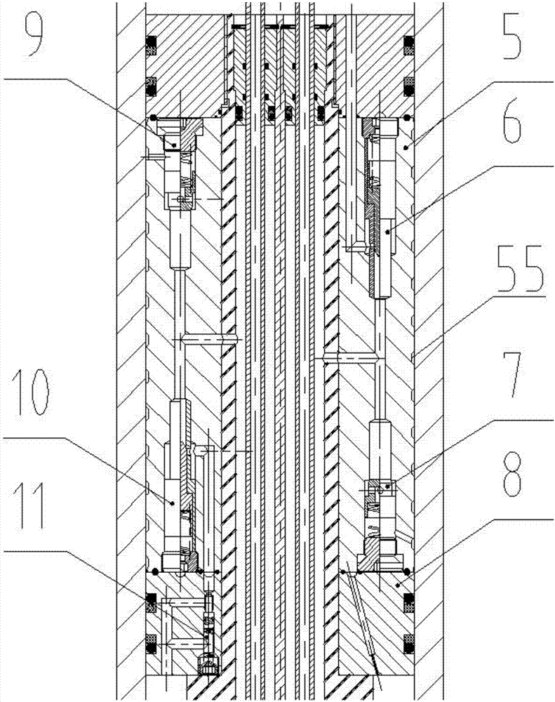
[0048] Such as Figures 1 to 8 shown. The invention discloses an integrated internal expansion type mechanical locking hydraulic outrigger, which includes a cylinder 3 and a piston rod 15 inside which also serves as a support; the piston rod 15 is controlled to perform telescopic movement through a hydraulic oil circuit control element; The piston of the piston rod 15 is divided into an upper end cover piston 4, a spiral sleeve 5 and a lower end cover piston 8; the upper end cover piston 4 is fixed on the piston rod 15 through threaded connection, and the lower end cover piston 8 and the spiral sleeve 5 are respectively set on the piston on the rod 15; the spiral sleeve 5 is limited and clamped between the upper end cap piston (4) and the lower end cap piston (8);

[0049] The outer circumferential surface of the spiral sleeve 5 is provided with a spiral groove cavity 55; the inside of the piston rod 15 is axially symmetrically opened with two oil guide holes; the first oil g...


PUM


Abstract

The invention discloses an integrated internal-expanding type mechanical-locking hydraulic supporting leg and an operating method thereof. The integrated internal-expanding type mechanical-locking hydraulic supporting leg comprises a cylinder barrel and a piston rod which is located in the cylinder barrel and also used as a supporting piece. A piston of the piston rod is divided into an upper end cover piston part, a spiral pipe sleeve and a lower end cover piston part. The upper end cover piston part is fixed to the piston rod. The piston rod is sleeved with the lower end cover piston part in a clearance fit mode. The piston rod is also sleeved with the spiral pipe sleeve in a clearance fit mode, and the spiral pipe sleeve is limited and clamped between the upper end cover piston part and the lower end cover piston part. A spiral grooved cavity is formed in the outer circumferential surface of the spiral pipe sleeve. Two oil guiding holes are symmetrically formed in the piston rod in the axial direction. A first oil guiding rod and a second oil guiding rod are connected into the two oil guiding holes correspondingly, and the spiral grooved cavity can be connected with an oil inlet / outlet path of the hydraulic supporting leg in a communicating mode through the first oil guiding rod and the second oil guiding rod. According to the integrated internal-expanding type mechanical-locking hydraulic supporting leg, all sequential motion functions of unlocking, stretching, locking, retreating, recovering and the like of the supporting legs are achieved in the way of integrating a plurality of hydraulic control elements in a piston assembly.

Description

technical field [0001] The invention relates to a hydraulic support device, in particular to an integrated internal expansion mechanical locking hydraulic support leg and an operating method thereof. Background technique [0002] In the hydraulic support leveling system of special heavy-duty engineering vehicles, in order to ensure the durability of support leveling accuracy, internal expansion mechanical locking hydraulic outriggers are generally used as the support leveling mechanism. In principle, the internal expansion mechanical locking outrigger requires that the mechanical lock must be released hydraulically before the telescopic adjustment function of the hydraulic outrigger can be realized. At present, the high-pressure unlocking oil circuit of the internal expansion mechanical locking hydraulic outrigger is generally set separately in the outrigger structure, and works independently of the oil inlet and oil return drive oil circuits of the outrigger. These three o...

Claims


Application Information

Patent Timeline
IPC IPC(8): F15B13/02F15B11/08B60S9/12
CPCF15B11/08F15B13/02B60S9/12
Inventor 丁问司陈康丁云柯
Owner SOUTH CHINA UNIV OF TECH
Why Eureka
Try Eureka