Fiber fixing clamp suitable for fixation of inclined planes

A technology for fixing cards and optical fibers, which is applied in the field of optical fiber communication, can solve the problems of easy drop of feeder lines and unreliable fixation, and achieve the effects of not easy to fall off, reliable fixation, and flexible position adjustment

Active Publication Date: 2017-11-21
锋迈(厦门)半导体科技有限公司
View PDF4 Cites 0 Cited by
  • Summary
  • Abstract
  • Description
  • Claims
  • Application Information

AI Technical Summary

Problems solved by technology

[0006] The feeder card for optical fiber is often composed of a C-type bracket and an optical fiber fixing part. The angle at the corner of the C-type bracket is usually a right angle, which is used to fix on the wall or other planes. However, the C-type with a right angle The fixing frame usually only has horizontal and vertical installation functions. In special occasions, such as when the wall is inclined or the feeder needs to bend, there are problems of unreliable fixation and the feeder is easy to fall

Method used


Image

  • Fiber fixing clamp suitable for fixation of inclined planes
  • Fiber fixing clamp suitable for fixation of inclined planes

Examples


Embodiment 1

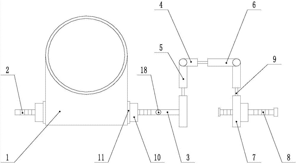
[0027] Such as figure 1 As shown, the optical fiber fixing jig suitable for fixing on an inclined plane includes an optical fiber sheath 1, and a screw 2 is installed through the optical fiber sheath 1, and the optical fiber sheath 1 and the screw 2 are screwed together, and the optical fiber sheath 1 can move along the screw 2 , one end of the screw rod 2 is hinged with a connecting rod 3, and the hinge can be fixed by a threaded fastener, and the end of the connecting rod 3 away from the screw rod 2 is provided with a C-shaped mount 4; the C-shaped mount 4 includes a mounting plate-5, installation Plate 2 6, mounting plate 3 7, the two ends of mounting plate 6 are respectively hinged with mounting plate 1 5 and mounting plate 3 7, and the hinges can be fixed by threaded fasteners, mounting plate 1 5 is far away from connecting rod 3 One end of the screw rod 2 is connected, the mounting plate 3 7 is penetrated with a compression screw 8, the compression screw 8 is screwed wit...

Embodiment 2

[0030] This embodiment is based on Embodiment 1 to further illustrate the present invention.

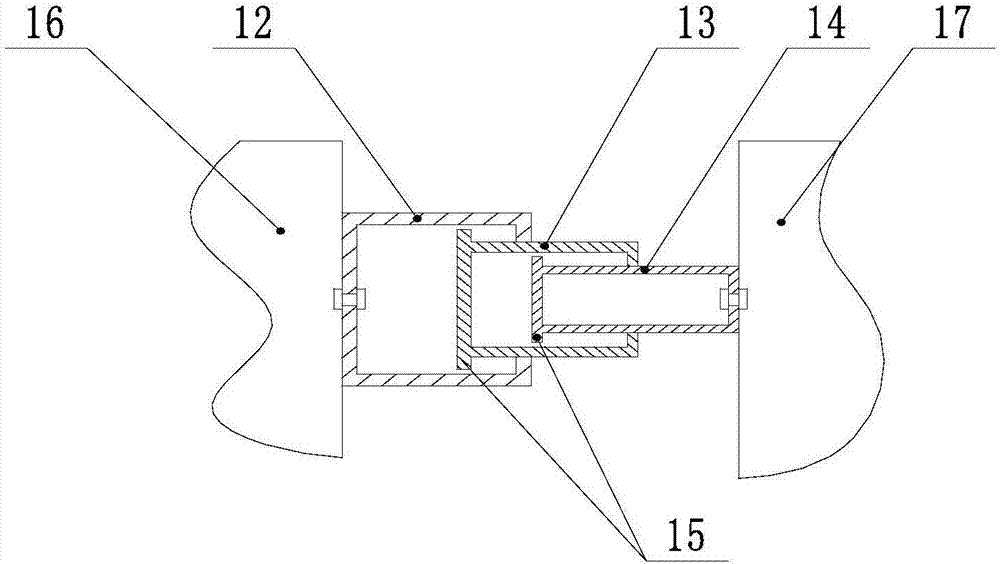
[0031] Such as figure 2As shown, the optical fiber fixing jig suitable for fixing on an inclined plane, the telescopic rod 9 includes a large cavity 12, a middle cavity 13 and a small cavity 14, and the length thereof increases successively, and one end of the large cavity 12 is connected to the flat plate 16, The other end is provided with an opening, the middle cavity 13 is located in the large cavity 12, and can move along the opening of the large cavity 12; the end of the middle cavity 12 located in the large cavity 12 is provided with a limiter 15, and the other end is provided with a Opening; the small cavity 14 is located in the middle cavity 13, and can move along the opening of the middle cavity 13; the end of the small cavity 14 located in the middle cavity 13 is also provided with a limiter 15, and the other end is connected to the flat plate 2 17 Above, the lengths of t...


PUM


Abstract

The invention discloses a fiber fixing clamp suitable for fixation of inclined planes. The clamp comprises a fiber sheath. A screw penetrates through the fiber sheath. The fiber sheath and the screw are screwed together. The fiber sheath is capable of moving along the screw. A connection rod is hinged to one end of the screw. The hinging place can be fixed through a screw fastening piece. One end, away from the screw, of the connection rod is equipped with a C-type fixing rack. The C-type fixing rack comprises an installation plate 1, an installation plate 2 and an installation plate 3. Two ends of the installation plate 2 are hinged to the installation plate 1 and the installation plate 3, and hinging places can be fixed through thread fastening pieces. One end of the installation plate is connected with one end, away from the screw, of the connection rod. A press screw penetrates through the installation plate 3. Each of the installation plate 1, the installation plate 2 and the installation plate 3 comprises a flat plate 1 and a flat plate 3. The flat plates 1 are connected with the flat plates 2 through telescoping rods. According to the invention, the clamp is suitable for fixation on multiple kinds of planes; positions of feed line cards can be quite flexibly adjusted; and feed lines can be fixed and are not liable to fall off.

Description

technical field [0001] The invention relates to the technical field of optical fiber communication, in particular to an optical fiber fixing jig suitable for fixing on inclined planes. Background technique [0002] With the application of optical fiber more and more widely, the development of optical fiber communication technology is also advancing by leaps and bounds. Optical fiber communication technology is also optical fiber communication technology. The principle is to use optical fiber to transmit signals to realize a communication method of information transmission. In practical applications The optical fiber communication system uses not a single optical fiber, but an optical cable composed of many optical fibers gathered together. [0003] The development of optical fiber communication is extremely rapid. By the end of 1991, 5.63 million kilometers of optical cables had been laid around the world, and by 1995 it had exceeded 11 million kilometers. Optical fiber com...

Claims


Application Information

Patent Timeline
Patent Type & Authority Applications(China)
IPC IPC(8): G02B6/46
CPCG02B6/46
Inventor 赖成军
Owner 锋迈(厦门)半导体科技有限公司
Why Eureka
Try Eureka