
Automatic electric water heater apparatus
An electric water heater, automatic technology, applied in the direction of preventing contact with live contacts, coupling devices, fluid heaters, etc., can solve the problems of poor plug stability, user electric shock, poor contact, etc., to achieve the effect of convenient connection
- Summary
- Abstract
- Description
- Claims
- Application Information
AI Technical Summary
Problems solved by technology
Method used
Image

Examples
Embodiment Construction
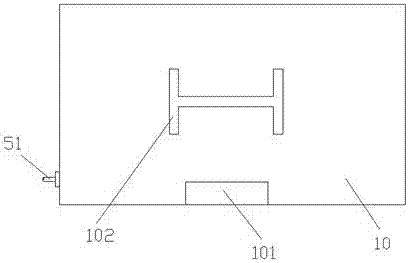
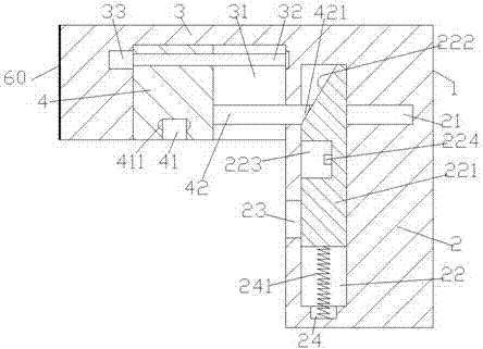
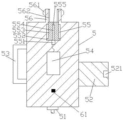
[0022] like Figure 1-Figure 6 As shown, an automatic electric water heater device of the present invention includes an electric water heater 10 and an electrical connection device. The electrical connection device includes an electrical connection terminal 1 and an electrical connection pin 5 composed of an insertion part 3 and an electrical connection part 2. The insertion part 3 is fixedly arranged at the upper left side of the electrical connection part 2. A slide rail groove 31 is provided in the end surface of the bottom of the entry part 3, and a first screw rod 32 extending left and right is provided in the slide rail groove 31, and the left end of the first screw rod 32 is connected with the first electric rotating machine 33, The right side end of the first screw rod 32 is connected with the inner end of the right side of the slide rail groove 31 in running cooperation, and the first screw rod 32 is provided with a connecting block 4 that is screw fit and connected. ...
PUM
 Abstract
Description
Claims
Application Information