Gynecological and obstetric emergency midwifery device

An obstetrics and gynecology, emergency technology, applied in the field of emergency obstetrical midwifery devices in obstetrics and gynecology, can solve problems such as inability to adjust knee flexion, secondary injury to the patient's body, and increase the difficulty of obstetric medical staff, so as to ensure safe production and avoid injury. Effect

Inactive Publication Date: 2017-12-01
胡迎章
View PDF8 Cites 7 Cited by
  • Summary
  • Abstract
  • Description
  • Claims
  • Application Information

AI Technical Summary

Problems solved by technology

[0002] Suction cup midwifery is often used for pregnant women whose second labor process is too long or the mother has special physical conditions. In the past, the suction cup midwifery method was performed by obstetric medical staff manually holding the delivery suction cup. Due to different medical staff's own skills Different from experience, it is easy to cause medical staff to use force carelessly during childbirth, which will hurt the fragile limbs of the newborn. Moreover, due to the different experience of medical staff in traditional midwifery methods, if the scar tear

Method used


Image

  • Gynecological and obstetric emergency midwifery device
  • Gynecological and obstetric emergency midwifery device
  • Gynecological and obstetric emergency midwifery device

Examples


Embodiment Construction

[0027] In order to make the technical means, creative features, goals and effects achieved by the present invention easy to understand, the present invention will be further described below in conjunction with specific embodiments.

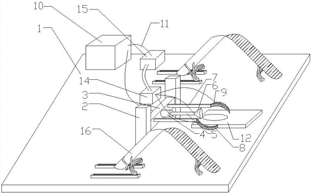
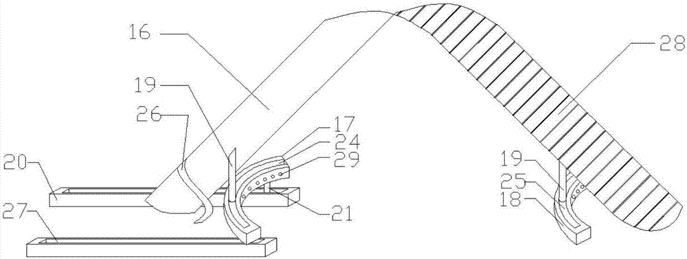
[0028] as attached Figure 1-6The emergency midwifery device for obstetrics and gynecology shown includes an operating table 1 on which a forceps assembly and two sets of knee bending angle adjustment assemblies are arranged; the forceps assembly includes two fixing columns 2 and two An elastic handle 7, a connecting rod 3 is arranged between the two fixed columns 2, and the two elastic handles 7 are horizontally and symmetrically fixed on the connecting rod 3, and the ends of the two elastic handles 7 away from the connecting rod 3 are all provided with There is a midwifery forceps 8, and the surface of the midwifery forceps 8 is provided with a uterine expansion air bag layer 9; the two groups of knee bending angle adjustment components are symm...


PUM


Abstract

The invention discloses a gynecological and obstetric emergency midwifery device, and relates to the technical field of medical apparatus and instruments. The gynecological and obstetric emergency midwifery device comprises a midwifery forceps assembly and two knee bending angle adjusting assemblies. The two knee bending angle adjusting assemblies are symmetrically arranged on two sides of the midwifery forceps assembly and comprise support plates, first arc-shaped slide rail assemblies, second arc-shaped slide rail assemblies, linear slide rail components and spring connecting pieces, two vertical support columns are arranged at two ends of the bottom of each support plate, the vertical support columns at the ends, which are far away from human bodies, of the support plates are slidably connected with the first arc-shaped slide rail assemblies, the vertical support columns at the ends, which are close to the human bodies, of the support plates are slidably connected with the second arc-shaped slide rail assemblies, and the spring connecting pieces are arranged at the bottoms of the first arc-shaped slide rail assemblies and are connected with the linear slide rail components in a rolling manner. The gynecological and obstetric emergency midwifery device has the advantages that the gynecological and obstetric emergency midwifery device can effectively assist delivery women to carry out labor, and secondary injury of the delivery women can be reduced; labor postures can be adjusted by the gynecological and obstetric emergency midwifery device according to the body types and the leg lengths of the delivery women.

Description

technical field [0001] The invention relates to the technical field of medical devices, in particular to an obstetrics and gynecology emergency midwifery device. Background technique [0002] Suction cup midwifery is often used for pregnant women whose second labor process is too long or the mother has special physical conditions. In the past, the suction cup midwifery method was performed by obstetric medical staff manually holding the delivery suction cup. Due to different medical staff's own skills Different from experience, it is easy to cause medical staff to use force carelessly during childbirth, which will hurt the fragile limbs of the newborn. Moreover, due to the different experience of medical staff in traditional midwifery methods, if the scar tear is caused during the midwifery process, it will be harmful to the patient. Secondary injuries to the body greatly increase the work difficulty of obstetrical medical staff. In addition, due to the different leg lengths...

Claims


Application Information

Patent Timeline
IPC IPC(8): A61G13/00A61G13/12A61G13/10
CPCA61G13/0009A61G13/107A61G13/1245A61G13/129A61G2200/12
Inventor 胡迎章侯春梅岳庆红李志强
Owner 胡迎章
Why Eureka
Try Eureka