New energy automobile device

A new energy vehicle and electric connection technology, applied in coupling devices, electric vehicles, electric vehicle charging technology, etc., can solve problems such as easy to cause electric shock accidents, induced electric shock accidents, exposed electric connection holes, etc., to achieve good power supply stability, Prevent electric shock accidents and increase safety

Inactive Publication Date: 2017-12-15
YICHANG HUIYIXING NEW ENERGY TECH CO LTD
View PDF4 Cites 34 Cited by
  • Summary
  • Abstract
  • Description
  • Claims
  • Application Information

AI Technical Summary

Problems solved by technology

[0002] At present, the charging of new energy vehicles is to directly insert the contactor connected to it into the electric connection hole of the charging pile body and then power on. The charging pile body will always be in a power-on state when connected to the mains, although this plug-in method is more convenient to operate. , but when the manual operation bumper is inserted into the electrical connection hole, an arc may be generated and an electric shock accident may be induced. In addition, when the new energy vehicle is not charging, the bumper is often pulled out from the electrical connection hole, which will cause the electrical connection hole In this way, it is easy to cause electric shock accidents, and there is a great potential safety hazard. Moreover, when pulling out the contact head manually, it not only needs to exert a large force on the contact head, but also generates an electric arc and induces an electric shock accident.

Method used


Image

  • New energy automobile device
  • New energy automobile device
  • New energy automobile device

Examples


Embodiment Construction

[0021] The preferred embodiments of the present invention will be described in detail below with reference to the accompanying drawings, so that the advantages and features of the present invention can be more easily understood by those skilled in the art, so that the protection scope of the present invention can be more clearly defined.

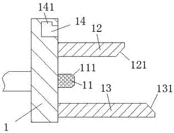
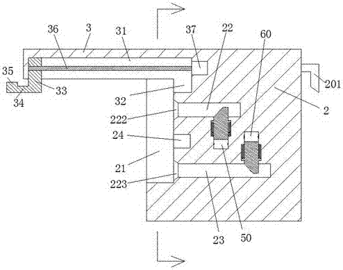
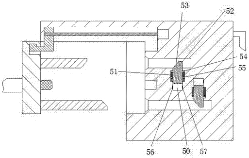
[0022] See Figure 1-5 A new energy vehicle device shown includes a charging gun connected to the new energy vehicle through a cable and a charging pile. The charging gun includes a pull plate 1, and the upper and lower ends of the right end surface of the pull plate 1 are symmetrically arranged with each other There are an upper insert plate 12 and a lower insert plate 13, the right end surfaces of the upper insert plate 12 and the lower insert plate 13 are respectively provided with an upper inclined surface 121 and a lower inclined surface 131, and the middle end of the right end surface of the pull plate 1 is arranged There is a bumper 11, ...


PUM


Abstract

The invention discloses a new energy automobile device, and the device comprises a charging gun and a charging pile body, which are connected with a new energy automobile through cables. The charging gun comprises a pull plate, and the upper and lower ends of the right end face of the pull plate are symmetrically provided with an upper plugboard and a lower plugboard. The right ends of the upper and lower plugboards are respectively provided with an upper inclined surface and a lower inclined surface. The central end of the right end face of the pull plate is provided with a contact, and the right end face of the contact is provided with a movement guide surface. The upper end of the pull plate is provided with a pull slot with the notch facing the right. The upper end wall of the pull slot is provided with a clamping groove. The charging pile body comprises a housing and an extending end disposed at the upper end of the left side of the housing. The whole device can complete the switching-off and switching-on of the contact through the operation of a driver, i.e., the switching-off and switching-on of the new energy automobile. The device is simple and convenient in operation, and the pulling and plugging of the contact are achieved through mechanical motion. There is no need of manual operation for the pulling of the contact, thereby saving the force and preventing an electric shock accident caused by the manual plugging and pulling.

Description

Technical field [0001] The invention relates to the field of new energy vehicles, in particular to a new energy vehicle device. Background technique [0002] At present, the charging of new energy vehicles is to directly insert the bumper connected with it into the electrical connection hole of the charging pile body and then energize. The charging pile body will always be in a energized state when connected to the mains, although this plugging method is more convenient to operate , But when manually operating the connector is inserted into the electrical connector hole, an arc may occur and an electric shock accident may be induced. In addition, when the new energy vehicle is not charging, the connector is often pulled out from the electrical connector hole, which will cause the electrical connector hole This will easily lead to electric shock accidents, and there is a greater safety hazard. Moreover, when manually pulling out the bumper, it is not only necessary to exert a larg...

Claims


Application Information

Patent Timeline
Patent Type & Authority Applications(China)
IPC IPC(8): H01R13/629H01R13/703B60L11/18
CPCB60L53/31H01R13/629H01R13/7036H01R2201/26Y02T10/70Y02T10/7072Y02T90/12
Inventor 潘绍合
Owner YICHANG HUIYIXING NEW ENERGY TECH CO LTD
Why Eureka
Try Eureka