Stereoscopic vision measurement manual mark point based on speckle image matching

A technology of stereo vision measurement and speckle image, applied in the field of vision measurement, to avoid deviation, meet glare interference suppression, and meet the needs of precise positioning of artificial markers

Inactive Publication Date: 2018-01-05
四川精视科技有限公司
View PDF10 Cites 12 Cited by
  • Summary
  • Abstract
  • Description
  • Claims
  • Application Information

AI Technical Summary

Problems solved by technology

[0005] The purpose of the present invention is to solve the problem of clear imaging and precise positioning of artificial marking points under the condition of glare interference in stereo vision measurement, and to provide a stereo vision measurement of artificial marking points based on speckle image matching

Method used


Image

  • Stereoscopic vision measurement manual mark point based on speckle image matching
  • Stereoscopic vision measurement manual mark point based on speckle image matching
  • Stereoscopic vision measurement manual mark point based on speckle image matching

Examples


Embodiment 1

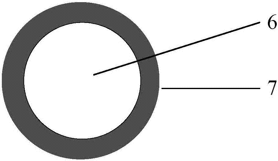
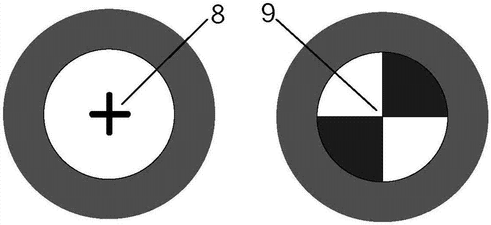
[0029] The artificial marking point pattern form that the present invention provides is in existing white circular artificial marking point (seeing figure 2 ) on the basis of adding a speckle pattern block to form a three-layer ring structure. Figure 4 A design example using rings and disks as ring pattern shapes is given, where 11 is the black ring on the outer layer, 12 is the white ring on the middle layer, and 10 is the speckle pattern block on the inner layer. The difference from the existing white circular artificial marking points is: 1) The black ring (11) on the outer layer is wider, which is more beneficial to cut off white glare. The specific width can be adjusted according to the application. When measuring a distance of one meter, it is recommended The width is more than 10mm; 2) The white ring (12) in the middle layer is relatively narrow, and the specific width can be adjusted according to the application. When measuring a distance of one meter, the recommende...

Embodiment 2

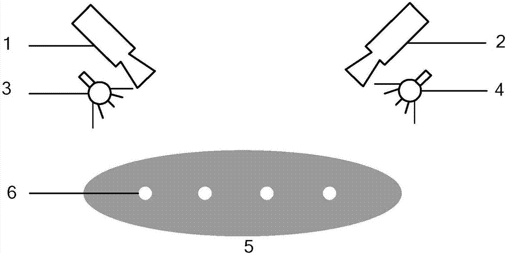
[0031] The three-dimensional measurement principle of the artificial marker point proposed by the present invention is: under the known situation of the image coordinates of the artificial marker point center (this center is defined as the circle center of the outer edge of the white circle) taken by the first camera, define a circle with a radius of ω disc, the disc is located in the speckle pattern block 10, as a reference speckle image, in the artificial marker image captured by the second camera, the corresponding matching point is found by digital speckle correlation method (DSCM), that is, Realize the extraction of the center image coordinates of the artificial marker points in the images captured by the two cameras, and then use the stereo vision calibration results to obtain the three-dimensional coordinates of the artificial marker points through 3D reconstruction.

[0032] In the actual measurement process, the captured artificial markers are not necessarily the ortho...

Embodiment 3

[0038] Embodiment 2 provides a basic method for locating artificial markers according to the present invention, and Embodiment 3 provides a method for quickly locating artificial markers. The difference from embodiment 2 is that in step 3, manual marker recognition is performed first, and then manual marker positioning is performed. The specific implementation method is to first detect the white rings in the white area, and then use the speckle pattern block judgment criterion to eliminate the white rings that do not contain speckle pattern blocks inside, and perform speckle image block matching in the remaining white rings. In this way, the search and matching range of the speckle image blocks can be reduced, the amount of image data processing can be reduced, and the matching speed can be improved. The judgment criterion of the speckle pattern block adopted is: ψ>ε, where ψ is the average gradient intensity of the pixels in the white circle, and ε is the judgment threshold, ...


PUM


Abstract

The invention discloses a stereoscopic vision measurement manual mark point based on speckle image matching. The manual mark point is a three-layer ring-shaped structure which is composed of a black ring in the outer, a white ring in the middle, and speckle patterns in the inner. A positioning method includes the following steps: firstly, in the process of testing an image, based on the information of the white ring and the speckle pattern blocks, detecting manual mark points; then conducting subpixel-level precision matching in a stereoscopic image by using a speckle image matching method; eventually based on the calibration result of a stereoscopic vision measurement system, conducting 3D construction to obtain the 3D coordinates of the manual mark points. According to the invention, themanual mark point pattern form and positioning method can effectively eliminate interference imposed by dazzling light on the surface of a to-be-tested target, and increase the robustness of a visionmeasurement system.

Description

technical field [0001] The invention belongs to the technical field of visual measurement, in particular to a stereoscopic vision measurement artificial marker point based on speckle image matching. Background technique [0002] The principle of stereo vision three-dimensional measurement technology is as follows: figure 1 As shown, two cameras (1, 2) and two light sources (3, 4) are used to paste a number of white circular artificial markers (6) on the surface of the measured object (5), and the two cameras are used to simultaneously shoot the measured The image of the artificial mark point on the surface of the object, locate the image coordinates of the center of the artificial mark point (6) in the measurement image, and obtain the three-dimensional coordinates of the center of the artificial mark point through three-dimensional reconstruction, and then realize the three-dimensional coordinate measurement on the corresponding position of the measured object, so as to obt...

Claims


Application Information

Patent Timeline
Patent Type & Authority Applications(China)
IPC IPC(8): G01B11/00
Inventor 不公告发明人
Owner 四川精视科技有限公司
Why Eureka
Try Eureka