Hydraulic cylinder for discharging device

A discharge device and hydraulic cylinder technology, applied in the field of hydraulic cylinders, can solve problems such as excessive impact force of workpieces, fast extension speed of hydraulic cylinders, damage, etc.

Active Publication Date: 2018-07-13
CHONGQING WEIQING HYDRAULIC MACHINERY CO LTD
View PDF6 Cites 3 Cited by
  • Summary
  • Abstract
  • Description
  • Claims
  • Application Information

AI Technical Summary

Problems solved by technology

[0004] The purpose of the present invention is to provide a hydraulic cylinder used in the discharge device to solve the problem that the hydraulic cylinder is extended too fast and the workpiece is suddenly damaged due to excessive impact force

Method used


Image

  • Hydraulic cylinder for discharging device
  • Hydraulic cylinder for discharging device

Examples


Embodiment Construction

[0018] The following is further described in detail through specific implementation methods:

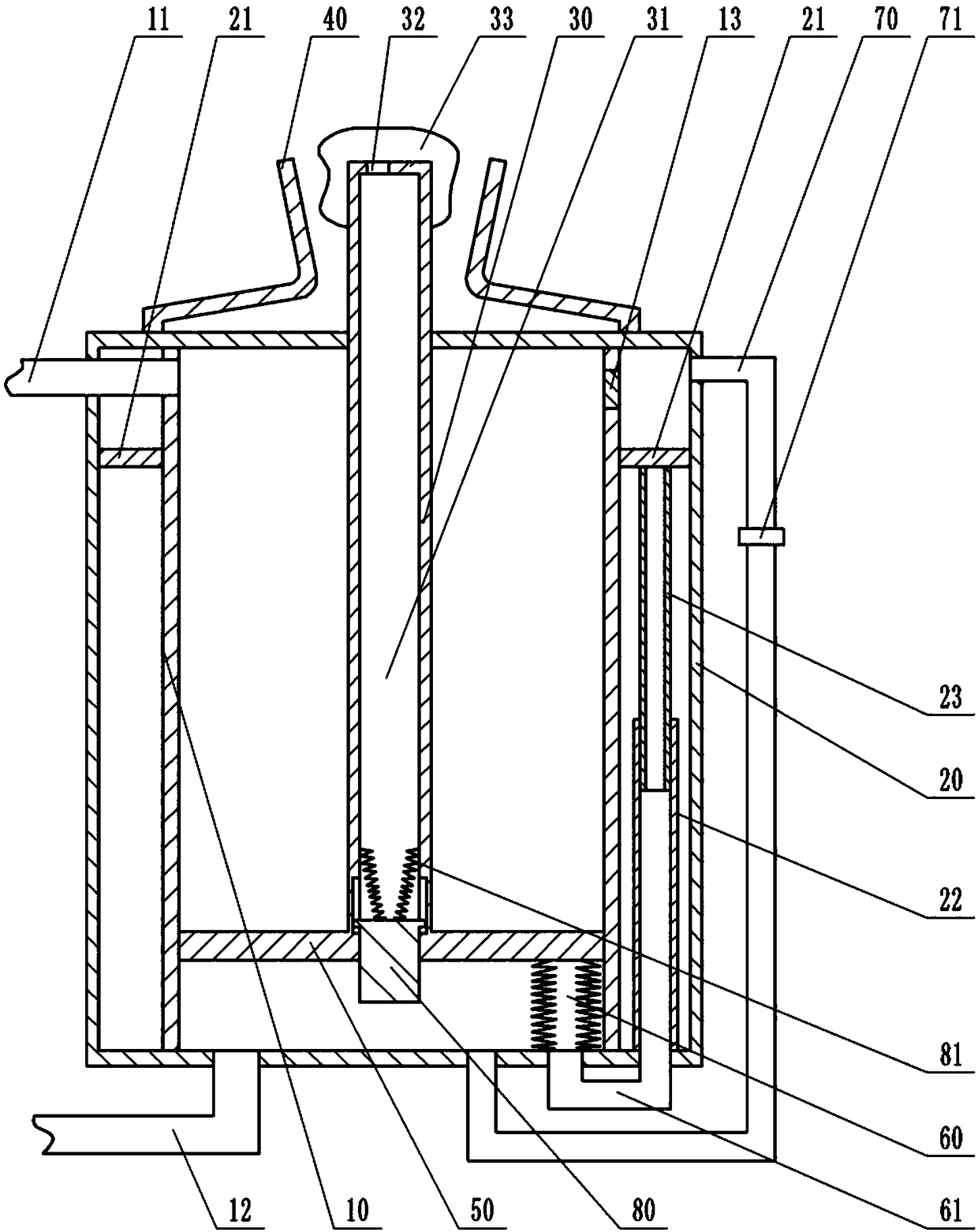
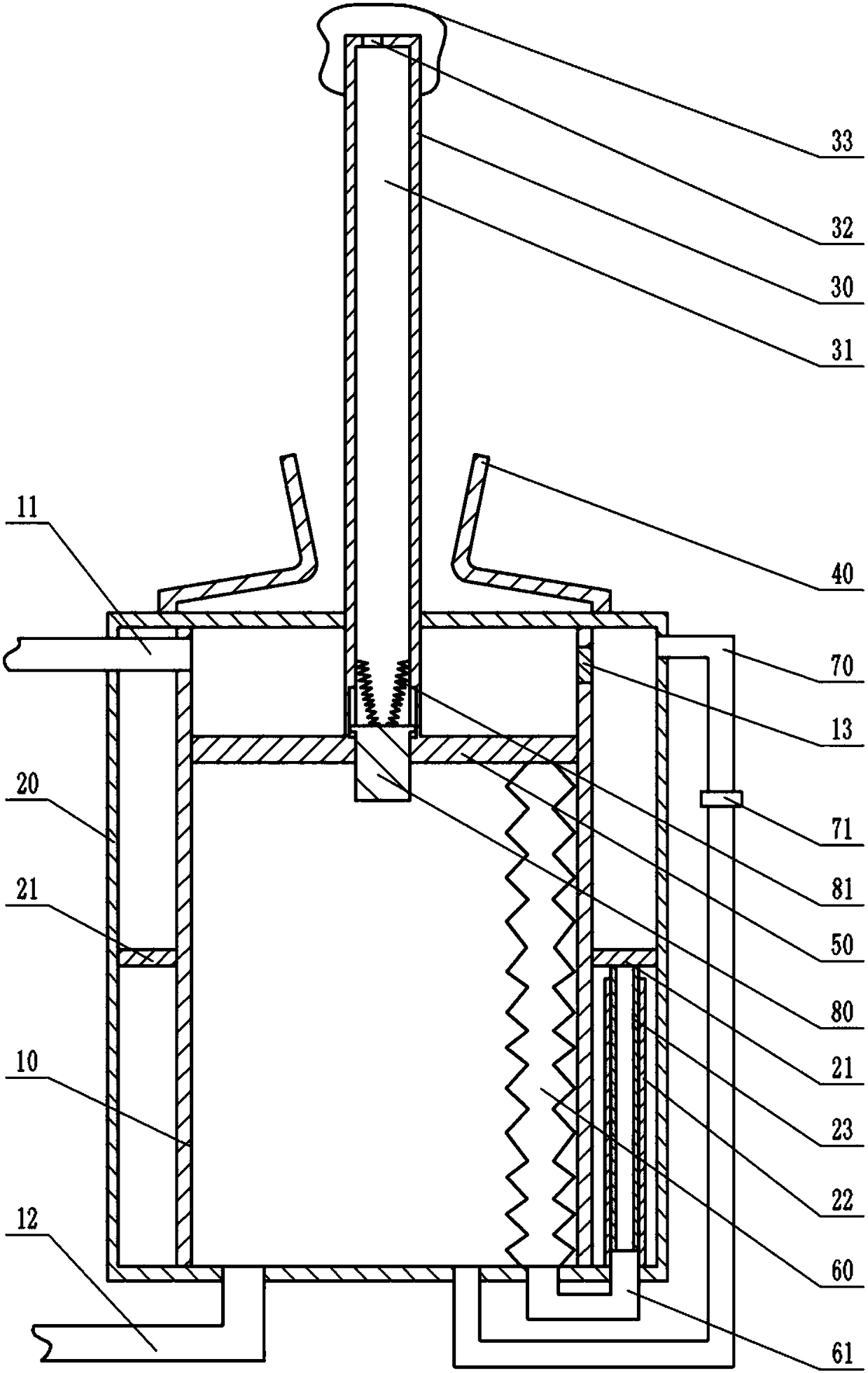
[0019] Instructions attached Figures 1 to 2 The reference signs in include: cylinder block 10, upper oil inlet passage 11, lower oil inlet passage 12, one-way oil discharge valve 13, outer cylinder 20, annular slide plate 21, fixed rod 22, sliding rod 23, piston rod 30, concave Cavity 31, through hole 32, air bag 33, sleeve 40, piston 50, rigid bellows 60, connecting pipe 61, oil pipe 70, one-way oil inlet valve 71, plunger 80, spring 81.

[0020] Such as figure 1 , figure 2 As shown, the hydraulic cylinder used for the discharge device includes a cylinder body 10, and the two ends of the cylinder body 10 are the cylinder bottom and the cylinder head respectively. The piston 50 is slid and sealed in the cylinder body 10, and the side of the piston 50 is fixed. There is a sealing ring attached to the inner wall of the cylinder body 10 . A piston rod 30 is fixed on the piston 50,...


PUM


Abstract

The invention belongs to execution elements in hydraulic systems, and particularly discloses a hydraulic cylinder for a discharging device. The hydraulic cylinder comprises a cylinder body, and a piston and a piston rod are arranged in the cylinder body. An upper oil inlet channel and a lower oil inlet channel are arranged on the cylinder body. An outer barrel is arranged on the outer portion of the cylinder body, an oil way is arranged between the cylinder body and the outer barrel, and an annular sliding plate is in sliding connection in the oil way. A telescopic rod is arranged in a lower oil cavity, and the upper end of the telescopic rod is connected with the annular sliding plate. A one-way oil draining valve is arranged on the upper portion of the cylinder body, the lower portion ofthe cylinder body is connected with an oil pipe, and a one-way oil inlet valve is arranged on the oil pipe. A concave cavity is formed in the piston rod, a plunger is in sliding connection in the concave cavity, and a spring is connected between the plunger and the piston rod. The upper portion of the piston rod is sleeved with an airbag. A sleeve is arranged on the upper portion of the cylinderbody, and the piston rod penetrates the sleeve. A rigid corrugated pipe is connected between the piston and the bottom of the cylinder body, and a connecting pipe is connected to the cylinder body. Bymeans of the technical scheme, the problem that due to the too high stretching speed of the hydraulic cylinder, a workpiece suddenly suffers from too large impact force and is damaged can be effectively solved.

Description

technical field [0001] The invention belongs to an actuator in a hydraulic system, in particular to a hydraulic cylinder used for a discharge device. Background technique [0002] The hydraulic cylinder is a hydraulic actuator that converts hydraulic energy into mechanical energy and performs linear reciprocating motion (or swinging motion). It has a simple structure and reliable operation. When it is used to realize reciprocating motion, the deceleration device can be eliminated and there is no transmission gap. , The movement is smooth, so it is widely used in various mechanical hydraulic systems. The output force of the hydraulic cylinder is proportional to the effective area of ​​the piston and the pressure difference on both sides; the hydraulic cylinder is basically composed of a cylinder barrel and a cylinder head, a piston and a piston rod, a sealing device, a buffer device and an exhaust device. [0003] In industrial production, because the hydraulic cylinder can ...

Claims


Application Information

Patent Timeline
Patent Type & Authority Applications(China)
IPC IPC(8): F15B15/16F15B15/22
CPCF15B15/1414F15B15/1457F15B15/16F15B15/22F15B15/226
Inventor 谷山品
Owner CHONGQING WEIQING HYDRAULIC MACHINERY CO LTD
Why Eureka
Try Eureka