Vehicle controller and control method thereof

A vehicle controller and control command technology, applied in the direction of program control, computer control, general control system, etc., can solve problems such as power supply redundancy control, and achieve the effect of simple system development, low cost, and high reliability

Pending Publication Date: 2018-11-13
UNITED AUTOMOTIVE ELECTRONICS SYST
View PDF5 Cites 1 Cited by
  • Summary
  • Abstract
  • Description
  • Claims
  • Application Information

AI Technical Summary

Problems solved by technology

[0004] The purpose of the present invention is to provide a vehicle controller and its control method to solve the problem of redundant power supply control in the existing vehicle controller

Method used


Image

  • Vehicle controller and control method thereof
  • Vehicle controller and control method thereof
  • Vehicle controller and control method thereof

Examples


Embodiment 1

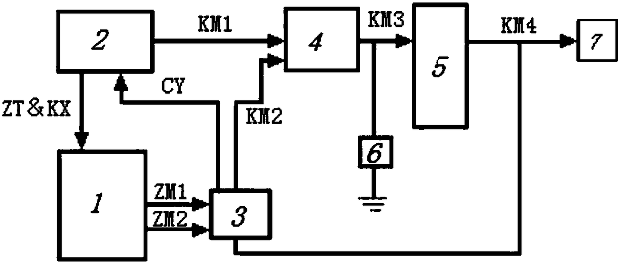
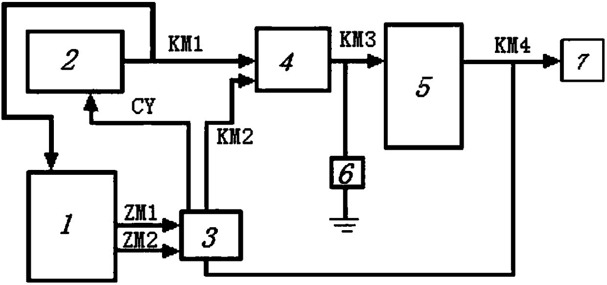
[0061] Such as figure 1 As shown, this embodiment provides a vehicle controller, which includes a central processing unit 1, a power control unit 2, a feedback circuit 3, an OR gate circuit 4 and a drive circuit 5, wherein: the power control unit 2 Send the first control command KM1 to the OR gate circuit 4, and the OR gate circuit 4 forms a power supply control signal KM3 according to the first control command KM1; the OR gate circuit 4 sends the drive circuit 5 the The power supply control signal KM3, the driving circuit 5 forms a power supply power signal KM4 according to the power supply control signal KM3, and sends it to the load 6; the driving circuit 5 sends the power supply power signal KM4 to the feedback circuit 3; The power control unit 2 also sends its own state information ZT to the central processing unit 1, and the central processing unit 1 controls the on-off of the feedback circuit 3 according to the state information ZT; , the feedback circuit 3 forms a se...

Embodiment 2

[0073] This embodiment provides a control method of a vehicle controller. The control method of the vehicle controller includes: the power supply control unit 2 sends the first control command KM1 to the OR circuit 4, and the OR circuit 4 transmits the first control command KM1 according to the first The control command KM1 forms a power control signal KM3; the OR circuit 4 sends the power control signal KM3 to the drive circuit 5, and the drive circuit 5 forms a power signal KM4 according to the power control signal KM3, and sends it to Load 6; the drive circuit 5 sends the power supply signal KM4 to the feedback circuit 3; the power supply control unit 2 also sends its own state information ZT to the central processing unit 1, and the central processing unit 1 according to the state The information ZT controls the on-off of the feedback circuit 3; when the feedback circuit 3 is on, the feedback circuit 3 forms a second control command KM2 according to the power signal KM4 of ...


PUM


Abstract

The invention provides a vehicle controller and a control method thereof; the vehicle controller control method comprises the following steps: a power supply control unit sends a first control order to an or gate circuit, the or gate circuit forms a power supply control signal according to the first control order; the or gate circuit sends the power supply control signal to a driving circuit, andthe driving circuit forms a power supply power signal according to the power supply control signal; the driving circuit sends the power supply power signal to a feedback circuit; the power supply control unit also sends self state information to a central processor, and the central processor controls the feedback circuit to connect / disconnect according to the state information; the feedback circuit forms a second control order according to the power supply power signal when the feedback circuit is conducted; the feedback circuit sends the second control order to the or gate circuit, and the orgate circuit continuously outputs the power supply control signal according to the second control order.

Description

technical field [0001] The invention relates to the technical field of automotive electronics, in particular to a vehicle controller and a control method thereof. Background technique [0002] At present, on the vehicle controller products, the power control function is realized by adding a power control chip, which cannot meet the functional safety design. When the power control chip fails, the power supply of the vehicle is suddenly interrupted. If the vehicle is driving at high speed, A power outage can lead to serious traffic accidents and consequences. Therefore, if you want to realize redundant control of the vehicle power supply, you need to achieve the output of dual power supply control signals, which often requires the use of dual power supply control chips, that is, two power supply control chips are used on the product to output a power supply control signal respectively. Realize the power control function. If one of the two chips fails and cannot output its own...

Claims


Application Information

Patent Timeline
Patent Type & Authority Applications(China)
IPC IPC(8): G05B19/042
CPCG05B19/0423G05B2219/25257G05B19/042
Inventor 周洁夏大卫秦承峰唐杰庆栋良
Owner UNITED AUTOMOTIVE ELECTRONICS SYST
Why Eureka
Try Eureka