Heat pipe

一种环路热管、热管的技术,应用在热管领域,能够解决无法起到稳流作用、流体难进入通过、影响流体换热等问题,达到降低噪声水平、提高稳流效果、强化传热的效果

Inactive Publication Date: 2018-11-16
SHANDONG UNIV
View PDF6 Cites 0 Cited by
  • Summary
  • Abstract
  • Description
  • Claims
  • Application Information

AI Technical Summary

Problems solved by technology

However, it was found during the operation of this device that the space A formed between the three pipes is relatively small because the pipes are tightly combined, because the space A is formed by the convex arc of the three pipes, so most of the space A Narrowness will make it difficult for the fluid to enter and pass through, resulting in a short circuit of the fluid, which affects the heat transfer of the fluid and cannot play a good role in stabilizing the flow
Simultaneously because the many tubes of above-mentioned structure are combined together, manufacture difficulty
[0007] In view of the above problems, the present invention has been improved on the basis of the previous invention, and a new heat pipe is provided, thereby solving the problems of low heat transfer coefficient and uneven heat transfer in the case of heat pipe heat exchange

Method used


Image

  • Heat pipe
  • Heat pipe
  • Heat pipe

Examples


Embodiment Construction

[0047] The specific embodiments of the present invention will be described in detail below in conjunction with the accompanying drawings.

[0048] In this article, if there is no special explanation, when it comes to formulas, " / " means division, and "×" and "*" mean multiplication.

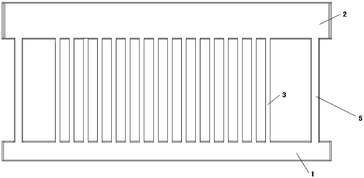
[0049] Such as figure 1 A heat pipe shown includes an evaporation header 1, a condensation header 2, a rising pipe 3 and a return pipe 5, the rising pipe 3 communicates with the evaporation header 1 and the condensation header 2, and the evaporation header 1 Located in the lower part, the condensation header 2 is located in the upper part, the fluid absorbs heat and evaporates in the evaporation header 1, enters the condensation header 2 through the riser 3, condenses after exchanging heat in the condensation header 2, and the condensed fluid Return to the evaporation header 1 through the return pipe 5.

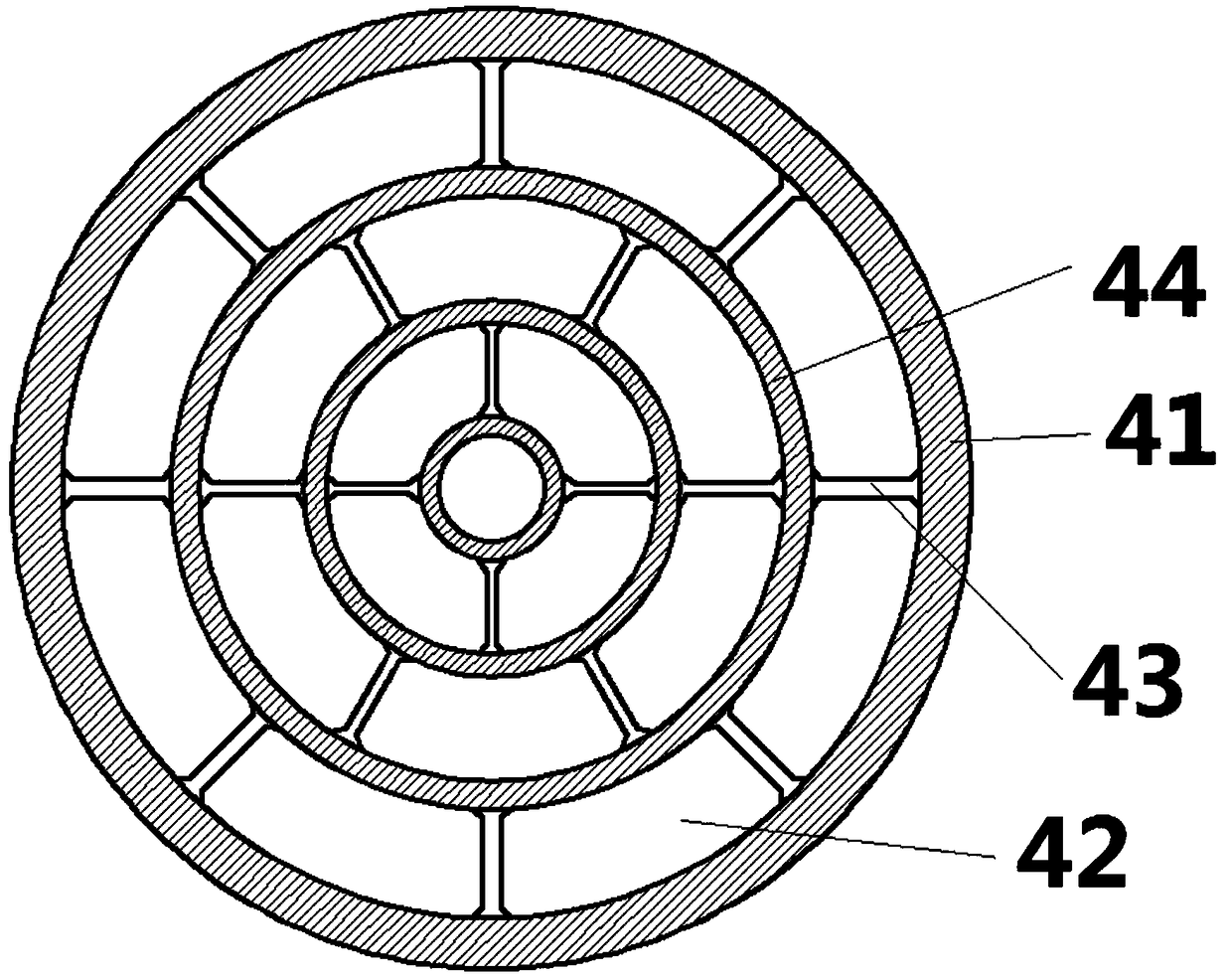
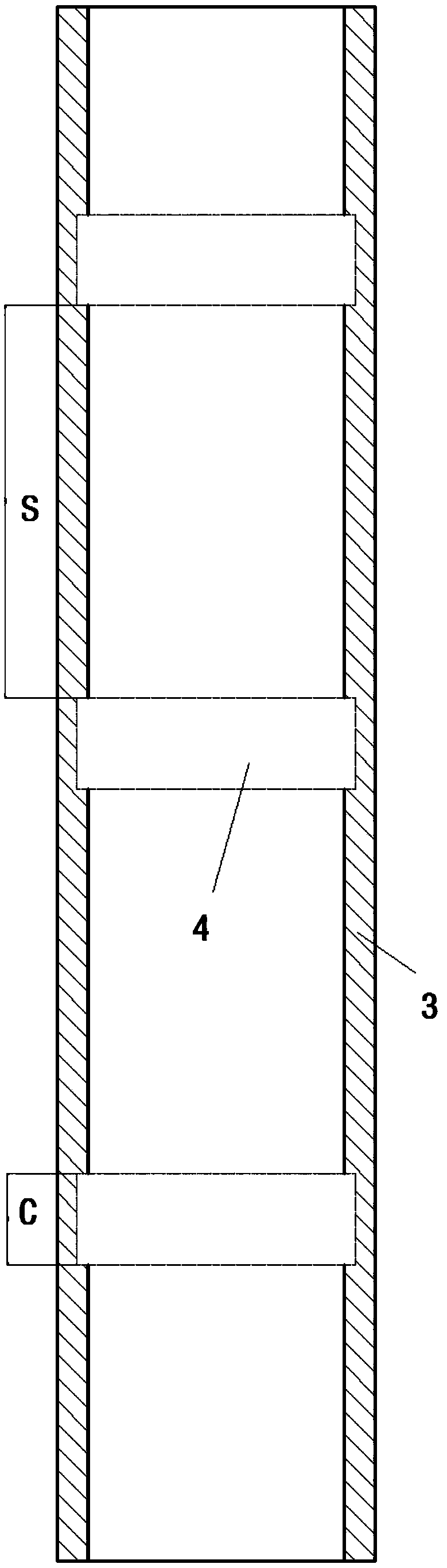
[0050] Such as Figure 4-5 As shown, an annular partition 4 is arranged in the riser 3 ....


PUM


Abstract

The invention provides a heat pipe which comprises an evaporation header, a condensation header, an ascension pipe and a return pipe, wherein a separating device is arranged in the ascension pipe; a groove is formed in the ascension pipe; and the shell of the separating device is arranged in the groove. Through the manner, the ascension pipe provided with the separating device is simple in manufacture and reduced in cost.

Description

technical field [0001] The invention belongs to the field of heat pipes, in particular to a heat exchange heat pipe. Background technique [0002] Heat pipe technology is a heat transfer element called "heat pipe" invented by George Grover of Los Alamos National Laboratory in the United States in 1963. It makes full use of the principle of heat conduction and phase change medium. The rapid heat transfer properties of the heat pipe quickly transfer the heat of the heating object to the heat source, and its thermal conductivity exceeds that of any known metal. [0003] Heat pipe technology was widely used in aerospace, military and other industries before. Since it was introduced into the radiator manufacturing industry, people have changed the traditional radiator design ideas and got rid of the single heat dissipation mode that only relies on high air volume motors to obtain better heat dissipation. The use of heat pipe technology enables the radiator to obtain a satisfacto...

Claims


Application Information

Patent Timeline
Patent Type & Authority Applications(China)
IPC IPC(8): F28D15/02
CPCF28D15/02F28D15/0266
Inventor 郭春生陈子昂高军宁淑荣孙蛟年显勃
Owner SHANDONG UNIV
Why Eureka
Try Eureka