Optical cable winding device

A winding device and optical cable technology, which can be used in transportation and packaging, delivery of filamentous materials, and thin material processing, etc. It can solve the problems of inconvenient storage for next use, lack of guiding winding function, and confusion in the winding of optical cables. , to achieve the effects of preventing back and forth swinging, facilitating wire release, and improving work efficiency

Inactive Publication Date: 2018-12-07
蔡玮
View PDF0 Cites 5 Cited by
  • Summary
  • Abstract
  • Description
  • Claims
  • Application Information

AI Technical Summary

Problems solved by technology

[0003] The object of the present invention is to provide a kind of winding device for optical cable, equipped with the ability to carry out simultaneous winding work on both sides of the optical cable, which greatly improves the efficiency of winding, and can also guide the winding or unwinding, which makes the work The efficiency is greatly improved, it is convenient for workers to use, and it has the advantages of very good practicability. It solves the problem that most of the winding devices currently used in the market have a single structure and do not have the function of guiding winding, which causes confusion in the winding process of the optical cable. , which brings great inconvenience to the next use or storage, delays the use of workers, and delays the construction period

Method used


Image

  • Optical cable winding device
  • Optical cable winding device

Examples


Embodiment Construction

[0015] The following will clearly and completely describe the technical solutions in the embodiments of the present invention with reference to the accompanying drawings in the embodiments of the present invention. Obviously, the described embodiments are only some, not all, embodiments of the present invention. Based on the embodiments of the present invention, all other embodiments obtained by persons of ordinary skill in the art without making creative efforts belong to the protection scope of the present invention.

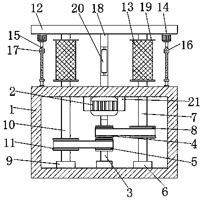
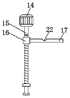
[0016] see Figure 1-2 , a winding device for an optical cable, comprising a box body 1, a motor 2 is fixedly connected to the top of the inner cavity of the box body 1, and a fixed block 21 is fixedly connected to both sides of the motor 2, and the top of the fixed block 21 is connected to the inner cavity of the box body 1. The top of the cavity is fixedly connected, through the setting of the fixed block 21, the vibration caused by the motor 2 can be reduce...


PUM


Abstract

The invention discloses an optical cable winding device which comprises a box body. The top of an inner cavity of the box body is fixedly connected with a motor. The bottom end of a rotating shaft ofthe motor is fixedly connected with a moving rod. The surface of the moving rod is sequentially sleeved with a first rotating barrel and a second rotating barrel from top to bottom. The right side ofthe bottom of the inner cavity of the box body is fixedly connected with a first bearing. The top of the first bearing is fixedly connected with a first rotating rod. According to the optical cable winding device, through cooperative use of the box body, the motor, the moving rod, the first rotating barrel, the second rotating barrel, the first bearing, the first rotating rod, a first belt disc, asecond bearing, a second rotating rod, a second belt disc, a top plate, winding rollers, positive and negative rotation motors, threaded rods, moving blocks, long rods and a vertical plate, the two sides of an optical cable can be wound and work at the same time, and the winding efficiency is greatly improved; guiding can also be carried out on winding or unwinding, and therefore the work efficiency is greatly improved, use by workers is convenient, and quite good practicality is achieved.

Description

technical field [0001] The invention relates to the technical field of optical cable winding, in particular to an optical cable winding device. Background technique [0002] Optical cables are manufactured to meet optical, mechanical or environmental performance specifications. It is a communication cable assembly that uses one or more optical fibers placed in a sheath as a transmission medium and can be used individually or in groups. Optical cables It is mainly composed of optical fibers, plastic protective sleeves and plastic sheaths. During the installation and maintenance of optical cables, it is often necessary to rewind the optical cables. Most of the rewinding devices currently on the market have a single structure and do not have guiding rewinding devices. Rolling function, the winding process causes the optical cable to be in a mess, which brings great inconvenience to the next use or storage, delays the use of workers, and delays the construction period. Content...

Claims


Application Information

Patent Timeline
Patent Type & Authority Applications(China)
IPC IPC(8): B65H54/54B65H54/44B65H54/20B65H54/28
CPCB65H54/54B65H54/20B65H54/2818B65H54/44B65H2701/32
Inventor 蔡玮
Owner 蔡玮
Why Eureka
Try Eureka