Optical fiber distribution cabinet

A technology of optical fiber wiring and optical fiber, which is applied in the field of optical fiber distribution cabinets, can solve problems such as fast search of unfavorable optical fibers, cross-winding, etc., and achieve the effects of shortening fault handling time, improving efficiency, and increasing search speed

Active Publication Date: 2019-01-01
LUOHE POWER SUPPLY OF HENAN ELECTRIC POWER CORP
View PDF17 Cites 3 Cited by
  • Summary
  • Abstract
  • Description
  • Claims
  • Application Information

AI Technical Summary

Problems solved by technology

[0008] 4. The staff have different pre-coiling techniques, and the coiling weight is different. Sometimes the jumper fiber will be coiled very tightly, and there will be cross-winding during the fiber coiling proces

Method used


Image

  • Optical fiber distribution cabinet
  • Optical fiber distribution cabinet
  • Optical fiber distribution cabinet

Examples


Embodiment 1

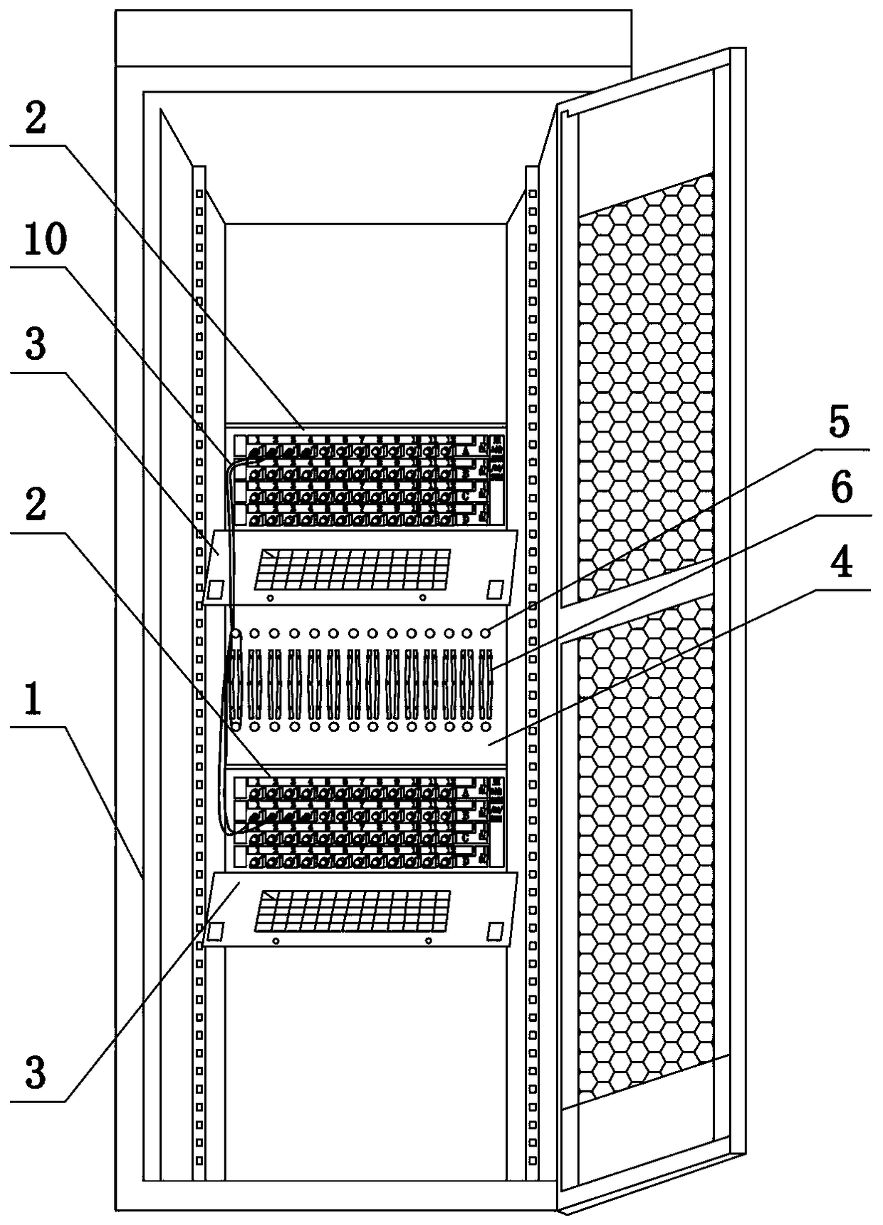
[0045] Such as figure 1 and figure 2 As shown, an optical fiber distribution cabinet in this embodiment includes a cabinet body 1, two distribution frames 2 arranged in the cabinet body 1, an optical fiber protection plate 3 installed on each distribution frame 2, and an optical fiber protection panel 3 Reserve wiring spacing between board 3 and distribution frame 2;

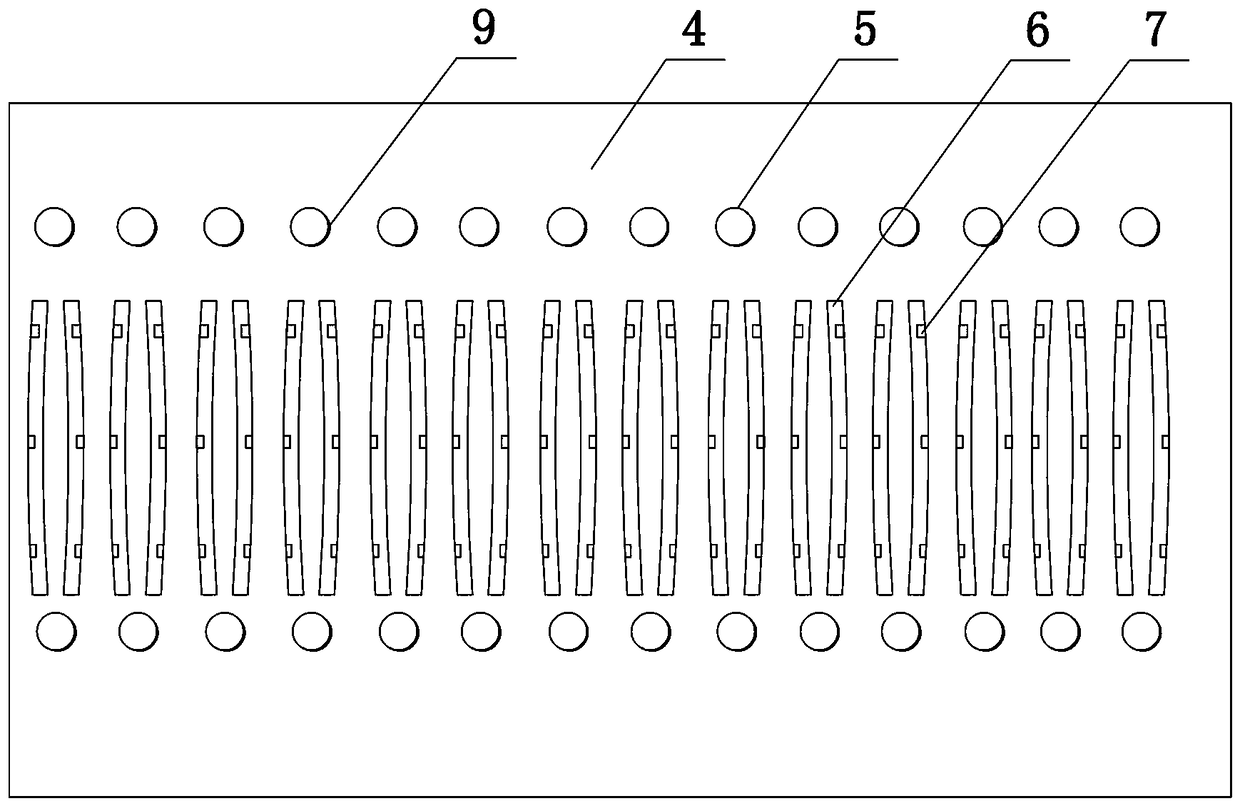
[0046]A winding mechanism is arranged between adjacent distribution frames 2, and the winding mechanism includes a winding plate 4, a plurality of winding posts 5 fixed on the winding plate 4 by threads or bolts, and a plurality of winding posts 5 set on the winding plate 4. The wire management groove 6 and the wire winding plate 4 are made of PVC plastic insulation board. The wire winding post 5 is integrally formed on the end face of the wire winding board 4. 5, every two cable management grooves 6 are a group, respectively adopt the arc combination of inner buckle type, which matches the shape of the oute...

Embodiment 2

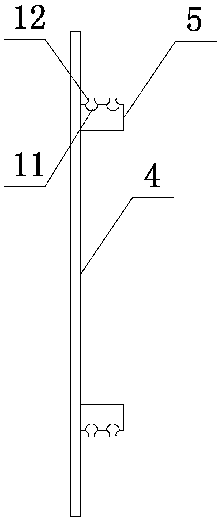
[0059] The structure of this embodiment is basically the same as that of Embodiment 1, the difference is: as image 3 As shown, the outer surface of the winding column 5 is provided with a plurality of winding grooves 11 matching the outer diameter of the optical fiber along its axial direction, and arc-shaped guide plates 12 are arranged on both sides of the winding groove 11, and the two sides of the same winding groove 11 The distance between the curved guide plates 12 is smaller than the outer diameter of the optical fiber.

[0060] Embodiment two

[0061] The structure of this embodiment is basically the same as that of Embodiment 2, the difference is: as Figure 4 As shown, an arc-shaped guide plate is jointly arranged between adjacent winding grooves, and the arc-shaped guide plate is a part of a circular plate or an oval plate.


PUM


Abstract

The invention belongs to the technical field of communication equipment, in particular to an optical fiber distribution cabinet. The cabinet comprises a cabinet body and a plurality of distribution frames in the cabinet body. A winding mechanism is disposed between the adjacent distribution frames. Each winding mechanism comprises a winding plate, a plurality of winding posts on the winding plate,a plurality of wire sorting grooves disposed on the winding plate, wherein the winding posts are arranged in two rows and multiple columns, and the wire sorting grooves are located between two columns of winding posts. Through the special design of the winding mechanisms, each two winding posts arranged at the top and bottom are set as one group, and the same group of optical fibers are wound around the same group of winding posts, thereby facilitating the reasonable winding of the remaining optical fibers, facilitating the fault inspection, greatly improving the searching speed, and shortening the fault processing time.

Description

technical field [0001] The invention belongs to the technical field of communication equipment, in particular to an optical fiber distribution cabinet. Background technique [0002] With the development of power communication, the communication equipment of the substation is becoming more and more perfect. Among these communication equipment, the optical fiber distribution cabinet plays a vital role. In the optical fiber distribution cabinet, the jumper connection of optical cables can be realized, so as to realize the inter-site business transmission. [0003] In optical transmission, the information communication of the two sites is connected through optical cables. If direct communication with the third site is required, it is necessary to use a jumper fiber to switch on the optical distribution, and then connect to the optical machine, and the optical machine connection also needs to be The light is equipped with a jumper. Generally, the jumper fiber is long. When the ...

Claims


Application Information

Patent Timeline
IPC IPC(8): G02B6/44
CPCG02B6/4441G02B6/4452G02B6/4457
Inventor 李亮胡兆宏刘海燕赵永浩刘晓燕田果
Owner LUOHE POWER SUPPLY OF HENAN ELECTRIC POWER CORP
Why Eureka
Try Eureka