Hydraulic Coupler

A hydraulic coupler and coupler technology, applied in clutches, clutches, fluid clutches, etc., can solve problems such as reducing the availability or durability of the coupler, the drain valve and its drive control cost.

Active Publication Date: 2021-08-20
VOITH PATENT GMBH
View PDF7 Cites 0 Cited by
  • Summary
  • Abstract
  • Description
  • Claims
  • Application Information

AI Technical Summary

Problems solved by technology

However, the venting valve and its actuation can be expensive and reduce the availability or durability of the coupling

Method used


Image

  • Hydraulic Coupler
  • Hydraulic Coupler
  • Hydraulic Coupler

Examples


Embodiment Construction

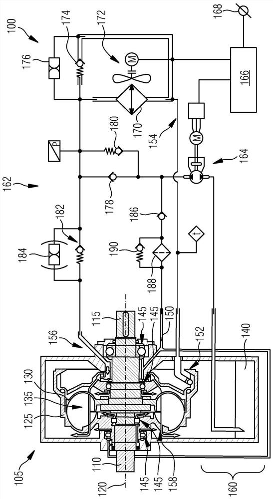
[0032] figure 1 A schematic diagram of a coupling system 100 with a fill-controlled fluid coupling 105 is shown. The coupling 105 is designed for controllably transmitting a rotational movement between an input side 110 and an output side 115 , which are mounted rotatably relative to each other about a common axis of rotation 120 . The coupling 105 includes a pump wheel 125 connected to the input side 110 and a turbine wheel 130 connected to the output side 115 . The pump wheel 125 and the turbine wheel 130 form a working chamber 135 in which a fluid 140 can be accommodated in order to hydraulically couple the turbine wheel 130 to the pump wheel 125 . In this case, the degree of coupling is related to the quantity of fluid 140 contained in the working chamber 135 . Pump wheel 125 and turbine wheel 130 are generally rotatably mounted by means of bearings 145 . For supplying the bearing 145 with fluid 140 a lubrication line 150 is provided. Fluid 140 may include aqueous or o...


PUM


Abstract

The filling-controlled hydraulic coupling comprises: a pump wheel and a turbine, which delimit the working chamber and which can be mechanically coupled to each other by means of hydraulic fluid; a direct circuit, which connects the hydraulic outlet of the working chamber with the hydraulic inlet; the pump means hydraulically arranged between the fluid source and the direct circulation; and a lubrication line leading from the pump means to the lubrication point of the coupling. In this case, the pump device is designed to convey fluid in a first conveying direction from the fluid source into the working chamber and into the lubrication line or to convey fluid in a second conveying direction from the working chamber to the fluid source.

Description

technical field [0001] The invention relates to a hydraulic coupling, which is also called a hydraulic coupling or a turbo coupling. In particular, the invention relates to a fill-controlled fluid coupling with direct circulation. Background technique [0002] The fluid coupling is designed to transmit torque between the input side and the output side. The input side is connected to the pump wheel and the output side is connected to the turbine, which delimit the working chamber. If the working chamber is filled with fluid, a hydrodynamic coupling occurs between the input-side and output-side rotational movements. In controlled fill couplers, the degree of coupling can be influenced by the amount of fluid in the working chamber. Usually, a filling pump is provided in order to deliver the fluid into the working chamber. A part of the transported fluid is shunted and directed to the lubrication points, especially the rolling bearings supporting the pump wheel or turbine. ...

Claims


Application Information

Patent Timeline
Patent Type & Authority Patents(China)
IPC IPC(8): F16D48/02F16D33/10
CPCF16D33/10F16D48/02F16D2048/0248F16D2048/029F16D2500/10487F16D2500/5014F16D2500/7045F16D2048/0269
Inventor 马库斯·莱伊迪格霍尔格·施米特斯特芬·约赫
Owner VOITH PATENT GMBH
Why Eureka
Try Eureka