Movable reinforcement machining shed structure

A steel structure and processing shed technology, applied in industrial buildings, building structures, buildings, etc., can solve the problems of being blown by the wind, the length of the steel bar processing shed is not easy to be too long, and it is not conducive to the promotion and use of the steel bar processing shed

Pending Publication Date: 2019-11-26
SINOHYDRO ENG BUREAU 4
View PDF0 Cites 2 Cited by
  • Summary
  • Abstract
  • Description
  • Claims
  • Application Information

AI Technical Summary

Problems solved by technology

[0003] The steel bar processing sheds in the prior art all adopt a fixed shed-like structure. Since the bottom surface area of ​​the steel bar processing shed is usually installed is limited, the length of the steel bar processing shed is not easy to be too long. If the length is too long, the hoisting equipment will only hoist the steel bar to be processed. To the side of the steel bar processing shed, the staff needs to transfer the processing to one end of the steel bar processing shed and then transport it to the steel bar processing shed for processing
And if the length of the steel bar processing shed is too short, although the steel bar to be processed can be hoisted to one end of the processing shed at one time, the steel bar to be processed will always be in an exposed state before processing, which is not conducive to the storage of the steel bar to be processed
In addition, due to the lack of corresponding protection measures for the steel bar processing sheds in the prior art, problems such as being blown by the wind often occur when they are used in coastal or other windy areas, which is not conducive to the large-scale promotion and use of steel bar processing sheds

Method used


Image

  • Movable reinforcement machining shed structure
  • Movable reinforcement machining shed structure
  • Movable reinforcement machining shed structure

Examples


Embodiment

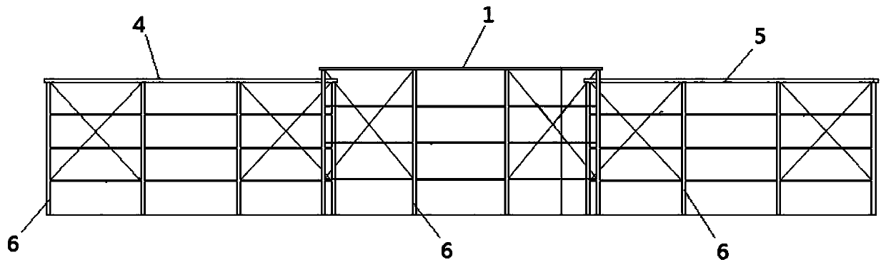
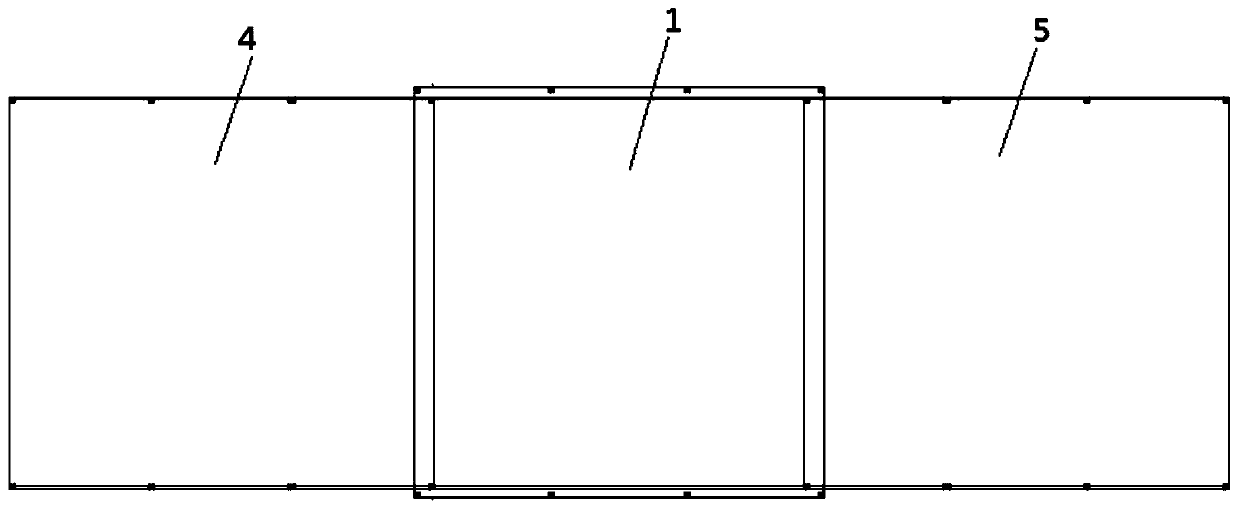
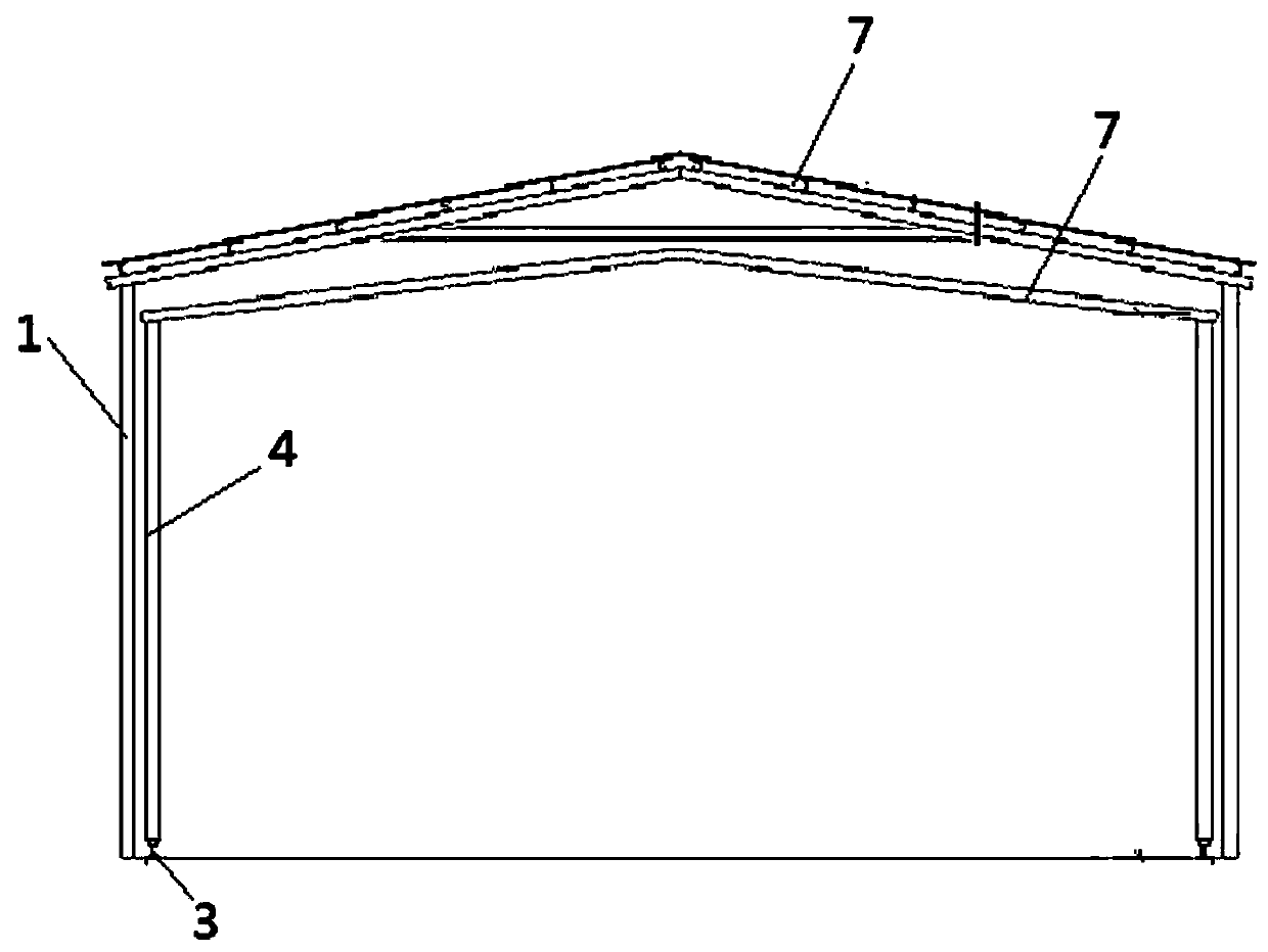
[0038] see figure 1 , figure 2 , image 3 , Figure 4 , Figure 5 , Image 6 , Figure 7 , Figure 8 , is a movable steel bar processing shed structure provided by the embodiment of the present invention, such as figure 1 , figure 2 , image 3 , Figure 4 , Figure 5 , Image 6 , Figure 7 , Figure 8 As shown, the structure includes a first steel structure shed main body 1, the first steel structure shed main body 1 is fixedly installed on the upper part of the hardened foundation 2; at least one gable end of the first steel structure shed main body 1 is missing to form an open structure; The above hardened foundation is made of C25 concrete.

[0039] A slide rail assembly, the slide rail assembly includes two parallel and separated slide rails 3 located on the upper part of the hardened foundation, and each end of the two slide rails 3 extends to the first steel rail through the open structure Inside the main body 1 of the structural shed; the two ends of th...


PUM

PropertyMeasurementUnit
Diameteraaaaaaaaaa

Abstract

The invention discloses a movable reinforcement machining shed structure. The movable reinforcement machining shed structure comprises a first steel structure shed body and a sliding rail assembly; the first steel structure shed main body is fixedly installed on the upper part of a hardening foundation; at least one end of the first steel structure shed body is not provided with a gable wall to form an open structure; the sliding rail assembly comprises two parallel and separated sliding rails located on the upper part of the hardening foundation, and one end of each of the two sliding rails extends into the first steel structure shed body through the open structure. The movable reinforcement machining shed structure is simple and reasonable in structure and convenient to install and use.The floor area is small, the storage of reinforcements to be machined and finished steel bars can be realized, hoisting and transfer of the steel bars to be processed and finished reinforcements cannot be affected. Meanwhile, the movable reinforcement machining shed structure has good wind resistance and can be applied to the occasion of strong wind, the scope of application of the reinforcement machining shed is greatly expanded, and popularization in a large area is worthy.

Description

technical field [0001] The invention relates to the technical field of work sheds, in particular to a movable steel bar processing shed structure. Background technique [0002] With the continuous improvement of the existing architectural design level, the gradual expansion of the project scale and the improvement of the functional requirements of the building, the demand for material processing on site is increasing. As the main material of building construction, steel bars mostly need to be processed on the construction site, and the working hours of the operators at the construction site are relatively long. In order to improve the operating environment, steel bar processing sheds came into being. [0003] The steel bar processing sheds in the prior art all adopt a fixed shed-like structure. Since the bottom surface area of ​​the steel bar processing shed is usually installed is limited, the length of the steel bar processing shed is not easy to be too long. If the lengt...

Claims


Application Information

Patent Timeline
IPC IPC(8): E04H5/02E04B1/343
CPCE04H5/02E04B1/34305
Inventor 周志强周艳平周效峰高用国王成江周百俊亢顺利
Owner SINOHYDRO ENG BUREAU 4
Why Eureka
Try Eureka