Movable dust collection device for electromechanical machining

A dust suction device and mobile technology, which is applied in the direction of combined devices, dispersed particle separation, chemical instruments and methods, etc., can solve problems such as clogging and inability to filter impurities, and achieve the effect of improving work efficiency and dust removal efficiency

Pending Publication Date: 2019-11-29
湖南志辉知识产权有限公司
View PDF1 Cites 2 Cited by
  • Summary
  • Abstract
  • Description
  • Claims
  • Application Information

AI Technical Summary

Problems solved by technology

The above-mentioned patents have the following disadvantages: impurities cannot be filtered during vacuuming, which is easy to cause blockage and cannot meet people's requirements

Method used


Image

  • Movable dust collection device for electromechanical machining
  • Movable dust collection device for electromechanical machining
  • Movable dust collection device for electromechanical machining

Examples


Embodiment 1

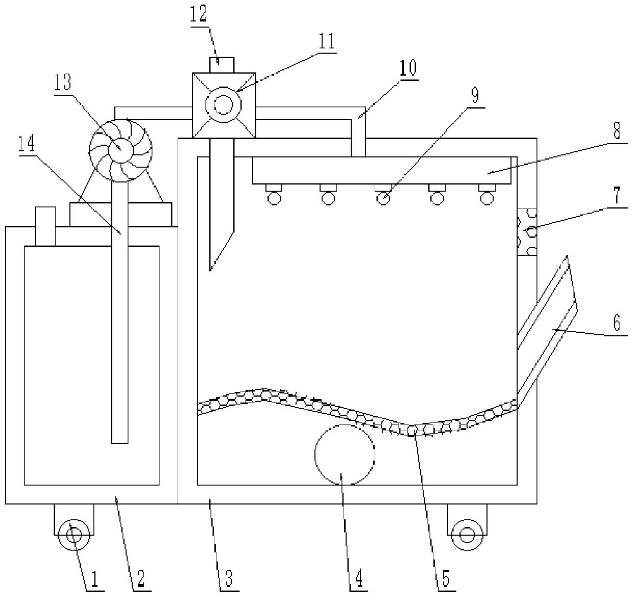
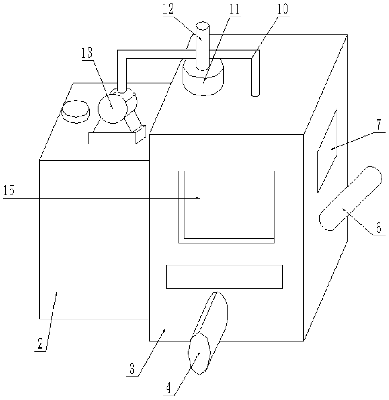
[0023] refer to figure 1 and figure 2 , a mobile vacuum device for electromechanical processing, including a water tank 2 and a box body 3, the bottom of the water tank 2 and the box body 3 are fixed with a plurality of wheels 1 by bolts, and the top outer wall of the water tank 2 is fixed by bolts There is a water pump 13, a water inlet pipe 14 is welded on the inner wall of the water inlet of the water pump 13, and a connecting pipe 10 is welded on the inner wall of the water outlet of the water pump 13, the bottom of the connecting pipe 10 is connected with the water outlet pipe 8, and the top of the box body 3 is fixed by bolts There is an air inlet fan 11, and the output end of the air inlet fan 11 is welded with an air inlet pipe 12, and the bottom of the air inlet pipe 12 is welded with the box body 3.

[0024] The water outlet pipe 8 is fixed on the top inner wall of the box body 3 by bolts, and the bottom of the water outlet pipe 8 is fixed with a plurality of nozzl...

Embodiment 2

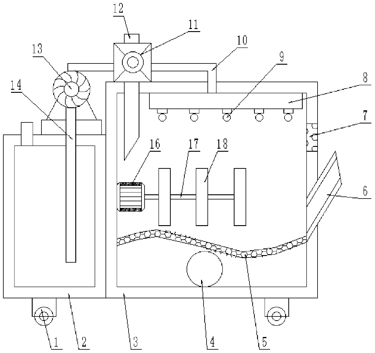
[0027] refer to image 3 , a mobile vacuum device for electromechanical processing. Compared with Embodiment 1, the main difference of this embodiment is that this embodiment also includes a submersible motor 16, which is fixed on one side of the box body 3 by bolts. On the inner wall, and one end of the output shaft of the submersible motor 16 is welded with a transmission rod 17, and one side of the transmission rod 17 is fixed with a plurality of stirring plates 18 by bolts.

[0028] The working principle of this embodiment: drive the transmission rod 17 and the stirring plate 18 to rotate through the submersible motor 16, promote the water flow in the box body 3, prevent impurities from adhering to the filter screen plate 5, and affect its normal drainage work, and can also Drive the circulation of air, so that the dust can be fully washed.


PUM


Abstract

The invention discloses a movable dust collection device for electromechanical machining. The device comprises a water tank and a box body, wherein a plurality of wheels are fixed to the bottom of thewater tank and the bottom of the box body through bolts; a water pump is fixed on the outer wall of the top of the water tank through bolts; a water inlet pipe is welded to the inner wall of a waterinlet of the water pump; a connecting pipe is welded to the inner wall of a water outlet of the water pump; a water outlet pipe is connected to the bottom of the connecting pipe; an air inlet fan is fixed to the top of the box body through bolts; an air inlet pipe is welded to the output end of the air inlet fan; and the bottom of the air inlet pipe is welded to the box body. According to the invention, external air can be extracted and quickly enter the box body for purification, so the working efficiency of the device is improved; water in the water tank can be extracted and is sprayed out through spray heads for cleaning air containing dust impurities, so the dust removal efficiency of the device is improved; and the device can filter out impurities, prevent the impurities from blockinga drainage pipe and thus prevent normal dust removal work from being affected by the blockage.

Description

technical field [0001] The invention relates to the technical field of dust collection devices, in particular to a mobile dust collection device for electromechanical processing. Background technique [0002] The industrial vacuum cleaner is a commonly used dust collection tool in the industry. Generally, the air with dust outside is first sucked in from the dust suction port on the dust collection bucket. When passing through the dust removal filter element, the dust is isolated outside the dust removal filter element. arrive. [0003] After retrieval, the authorized publication number is CN205732232U patent, which discloses a mobile dust collection device, including a vacuum cleaner housing, and a first filter cartridge installed in the vacuum cleaner housing, between the vacuum cleaner housing and the first filter cartridge A cyclone device is provided, the outlet at the lower end of the cyclone device is located below the first filter cartridge, the vacuum cleaner housi...

Claims


Application Information

Patent Timeline
Patent Type & Authority Applications(China)
IPC IPC(8): B01D50/00
CPCB01D50/60
Inventor 潘海军张文昭刘志壮高朕
Owner 湖南志辉知识产权有限公司
Why Eureka
Try Eureka