A support mechanism and a work vehicle with the support mechanism

A technology of support mechanism and support end, which is used in vehicle maintenance, lifting vehicle accessories, transportation and packaging, etc., and can solve the problems of complex system and cumbersome operation.

Active Publication Date: 2021-06-18
CHANGSHA ZHONGLIAN HENGTONG MACHINERY
View PDF0 Cites 0 Cited by
  • Summary
  • Abstract
  • Description
  • Claims
  • Application Information

AI Technical Summary

Problems solved by technology

[0008] The purpose of the present invention is to overcome the system complexity and cumbersome operation caused by the use of two independent systems for the vehicle body supporting device and the body erecting device in the prior art, and to provide a single telescopic part to complete the swinging of the supporting legs and the body erecting device. Erect two-action supporting mechanism

Method used


Image

  • A support mechanism and a work vehicle with the support mechanism
  • A support mechanism and a work vehicle with the support mechanism
  • A support mechanism and a work vehicle with the support mechanism

Examples


Embodiment 1

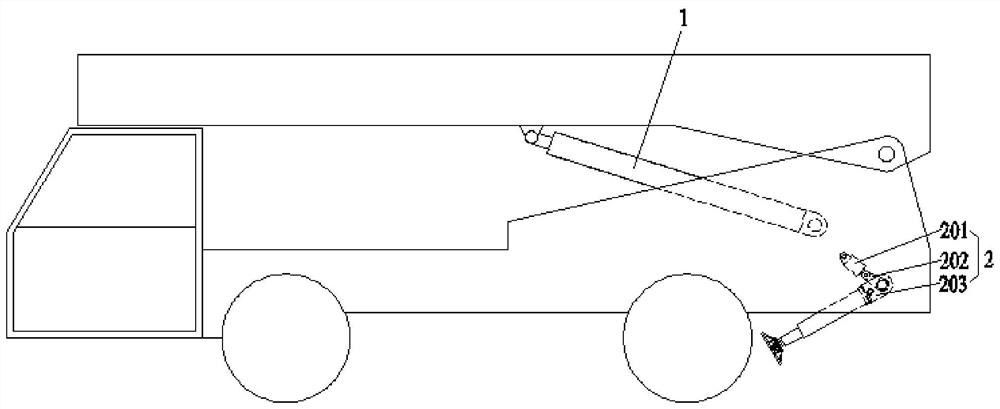
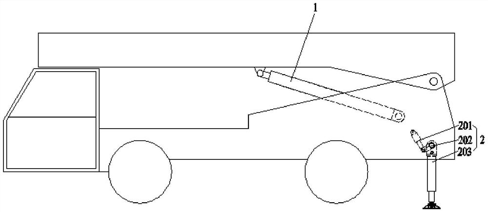
[0052] Such as figure 1 with figure 2 Distance figure 1 Schematic diagram of the initial state structure of the support leg 203 for the existing support mechanism, figure 2 Schematic structural diagram of the state structure for the support leg 203 of the existing support mechanism, from figure 1 with figure 2 This existing support mechanism is seen from two independent systems, one is the body support, and the second is vertical.

[0053] The vehicle body support device 2 is configured to support the vehicle to prevent the vehicle from being tipped, using the leg swing hydraulic cylinder 201 to connect the leg 203, and there is a intermediate link 202 between the two, and the retractable of the hydraulic cylinder 201 through the leg swing. The intermediate link 202 is rotated, and the intermediate link 202 drives the support leg 203 that is fixed to the intermediate link 202 for rotation, and the support leg 203 is rotated to the horizontal surface to support the vehicle support....

Embodiment 2

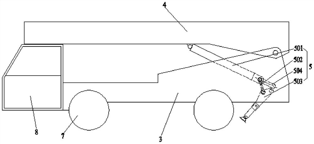
[0081] Such as image 3 with Figure 4 As shown, a working vehicle with a support mechanism is applied to the support mechanism as described in Example 1:

[0082] One end of the vertical drain member 501 is hinged to the upper 4 of the vehicle, and the other end is hinged to one end of the connecting rod 502, and the other end of the connecting rod 502 is connected to the shaft or support end of the leg 503. One end of the leg 503 is hinged to the frame 3 opposite the support end, and the frame 3 is attached to the end of the two at the end of the two;

[0083] The support mechanism further includes a strip bit structure 504 that limits the mild leg of the hinge 505 of the connecting rod 502 to control the hinge 505 to control the support 503 swing angle;

[0084] The hinge point of the vertical drain member 501 and the upper 4 can be disposed in the middle of the upper portion 4, the hinge point of the leg 503 and the frame 3 can be disposed at the tail of the frame 3, the strip l...


PUM


Abstract

The present invention relates to the technical field of transportation and loading and unloading, in particular to a support mechanism and a working vehicle with the support mechanism. One end is hinged with one end of the connecting rod, the other end of the connecting rod is connected with the shaft or the supporting end of the supporting leg, and the opposite end of the supporting leg is hinged with the vehicle frame. When working, the erecting telescopic part expands and contracts, and the hinged end of the erecting telescopic part and the connecting rod will move in the strip-shaped limiting structure, driving the outrigger to swing, and controlling the movement distance of the supporting leg in the bar-shaped limiting structure. According to the swing angle of the legs, after the swing is completed, the vertical expansion parts drive the upper body to rotate and dump. Using this structure to replace the independent outrigger swing system and the independent body erecting system simplifies the control and operation, the outrigger swing and the body erecting process are coherent, saves the operation conversion time, and solves the problem of traditional support mechanism control and manipulation. cumbersome question.

Description

Technical field [0001] The present invention relates to the field of transportation loading and unloading techniques, and more particularly to a support mechanism, and a work vehicle with a support mechanism. Background technique [0002] The support mechanism of the existing transport vehicle includes the vehicle body support and the vertical two independent systems, and when the loading is loaded, the operation of the dump loading is required to be operated separately. [0003] The stand-alone vertical device is used to pour the loader, and when the upper hydraulic cylinder 1 is connected to the frame 3 and the upper supply of the hydraulic cylinder 1, the outer mold 4 is rotated by the frame 3 as the fulcrum, thereby completing the dump of the loading. . The independent vehicle support device 2 is used to support the vehicle to prevent the vehicle from being tipped, using the leg swing hydraulic cylinder 201 connected to the support leg 203, and there is a intermediate link 20...

Claims


Application Information

Patent Timeline
Patent Type & Authority Patents(China)
IPC IPC(8): B60S9/10
CPCB60S9/10
Inventor 张虎刘龙兵徐驰宋院归
Owner CHANGSHA ZHONGLIAN HENGTONG MACHINERY
Why Eureka
Try Eureka