Ball sealing structure and hydraulic valve

A sealing structure and hydraulic valve technology, applied in the valve shell structure, fluid pressure actuation device, valve details, etc., can solve the problems of sealing failure, high pressure oil leakage, lack of

Pending Publication Date: 2020-01-21
杭州富阳孙氏机床有限公司
View PDF0 Cites 0 Cited by
  • Summary
  • Abstract
  • Description
  • Claims
  • Application Information

AI Technical Summary

Problems solved by technology

For ultra-high pressure working conditions, due to the severe impact of high-pressure hydraulic oil on the O-ring, the O-ring is easily washed away. When the ball returns to the sealing position, the high-pressure oil will leak due to the lack of sealing of the O-ring, resulting in O The sealing ring fails when it is in a static state, so only a hard seal structure can be used between the valve core and the ball
[0003] At present, the hard seal structure of the spool and the ball is mainly divided into three types: the first one is that the edge of the valve port of the flow channel of the spool collides with the sphere to form a line seal, but because the edge of the valve port is easy to A gap will be generated, which will lead to seal failure; the second is to set a conical sealing surface at the flow passage of the valve cor

Method used


Image

  • Ball sealing structure and hydraulic valve
  • Ball sealing structure and hydraulic valve
  • Ball sealing structure and hydraulic valve

Examples


Example Embodiment

[0024] In the following, the present invention will be described in detail and completely through specific embodiments in conjunction with the accompanying drawings.

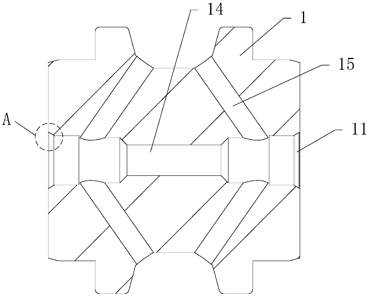
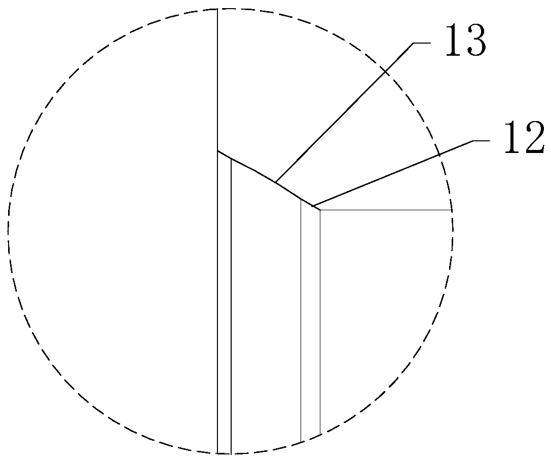
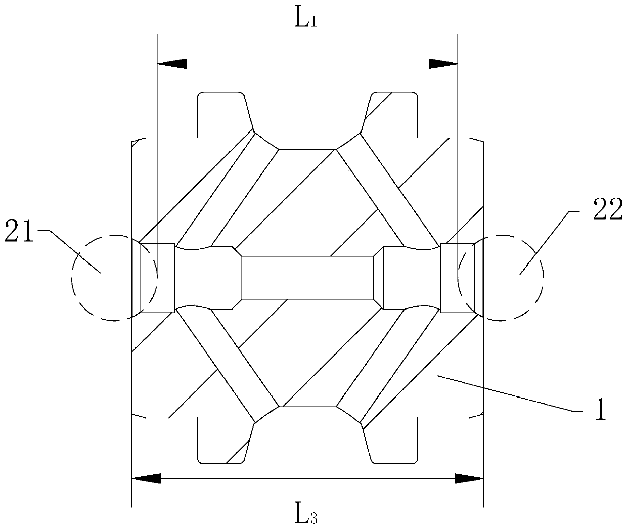
[0025] Please refer to Figure 1-5 As shown, the present invention provides a spherical body sealing structure, including a spherical body and a first valve core 1, the surface of the first valve core 1 is provided with a valve port 11, the inner hole diameter of the valve port 11 is smaller than the diameter of the sphere, and the valve port 11 is provided with a valve port 11. There is a conical sealing surface 12, and the conical sealing surface 12 is provided with a circular arc sealing surface 13 that is consistent with the circular arc surface of the sphere. to form a sealing structure. When the sphere blocks the valve port 11, the sphere can abut on the arc sealing surface 13 to form a surface seal, the sealing structure is reliable, and compared with the way of directly disposing the arc sealing surface...


PUM


Abstract

The invention discloses a ball sealing structure. The ball sealing structure comprises a ball and a first valve element, wherein a valve port is formed in the surface of the first valve element; the diameter of the valve port is smaller than that of the ball; a conical sealing face is arranged at the valve port; an arc sealing face consistent with the arc face of the ball is arranged on the conical sealing face; and the ball abuts against the arc sealing face so that the sealing structure can be formed. The ball sealing structure and a hydraulic valve are reasonable in design, simple in structure and capable of achieving sealing under the ultrahigh pressure and multi-dust working conditions.

Description

technical field [0001] The invention relates to the technical field of ultra-high pressure components, in particular to a ball sealing structure and a hydraulic valve. Background technique [0002] The hydraulic valve is an automatic component operated by pressure oil. It is controlled by the pressure oil of the pressure distribution valve and can be used to control the on-off of oil, gas and water pipeline systems. The common structure of the hydraulic valve is: a sphere is set at the front end of the flow channel of the spool, when the hydraulic oil flows forward, the flow pressure of the fluid can break the sphere, and the hydraulic oil can flow normally; when the hydraulic oil flows reversely , the ball will block the flow channel to form a cut-off effect and prevent the reverse flow of hydraulic oil. For ultra-high pressure working conditions, due to the severe impact of high-pressure hydraulic oil on the O-ring, the O-ring is easily washed away. When the ball returns ...

Claims


Application Information

Patent Timeline
IPC IPC(8): F15B13/02F16K15/04F16K27/02
CPCF15B13/027F16K15/04F16K15/048F16K27/0209
Inventor 孙钰昭
Owner 杭州富阳孙氏机床有限公司
Why Eureka
Try Eureka