A Pneumatic Gripper Device with Sensor Control

A pneumatic fixture and sensor technology, applied in workpiece clamping devices, manufacturing tools, etc., can solve the problems of mass production of unfavorable sensors, low production efficiency and high cost, and achieve the effects of simple structure, improved production efficiency and low input cost.

Active Publication Date: 2021-04-30
KELI SENSING TECH NINGBO CO LTD
View PDF14 Cites 0 Cited by
  • Summary
  • Abstract
  • Description
  • Claims
  • Application Information

AI Technical Summary

Problems solved by technology

[0004] The present invention mainly aims at the problems of low production efficiency and high cost of the existing clamps, which are not conducive to the mass production of sensors, and provides a pneumatic clamp device with sensor control which is high in production efficiency, low in cost and conducive to the mass production of sensors

Method used


Image

  • A Pneumatic Gripper Device with Sensor Control
  • A Pneumatic Gripper Device with Sensor Control
  • A Pneumatic Gripper Device with Sensor Control

Examples


Embodiment 1

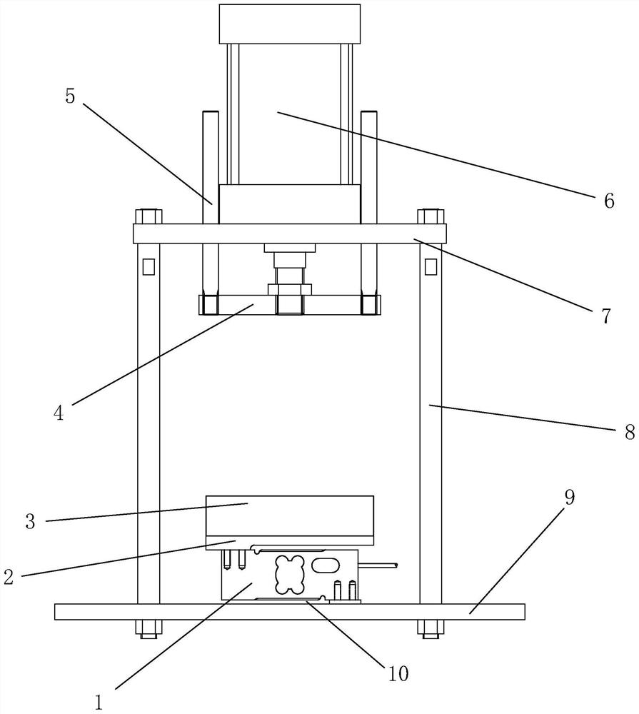
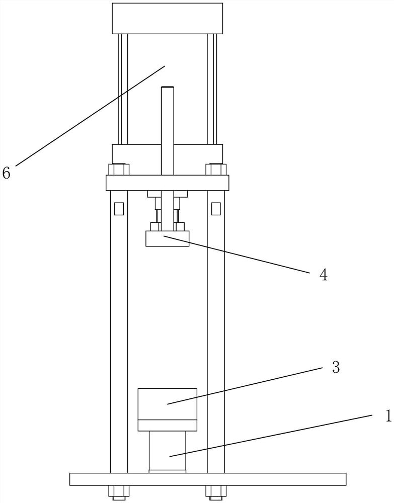
[0020]Such asfigure 1 ,2As shown, a pneumatic clamp device controlled by a sensor 1 includes a lower bottom plate 9 and a lower bottom plate 7, a lower bottom plate 9 and a upper bottom plate 7, and a cylinder 6 is attached to the upper bottom plate 7, the upper bottom plate 7 is mounted on the upper bottom plate 7, the piston of the cylinder 6 After the 16 rod passes through the upper bottom plate 7, the top plate 4 is connected, and the lower bottom plate 9 is provided with a sensor 1 for measuring the clamping force of the clamp, and the sensor 1 is called the heavy force sensor 1, which is convenient, and the output value is accurate. Sex, the sensor 1 is provided with a pressure plate 2 for placing the clamp, and the top plate 4 is pressed by the piston 16 rod on the cylinder 6, and the sensor 1 output force value is obtained to control the clamp value of the top plate 4, The clamping force is adjusted and controlled with the size of the sensor 1 output force, thereby improving...


PUM


Abstract

The invention relates to the field of automatic control of weighing sensor production, in particular to a pneumatic clamp device with sensor control. A pneumatic clamping device with sensor control, comprising a lower base plate and an upper base plate, the lower base plate and the upper base plate are connected by a column, an air cylinder is installed on the upper base plate, and the piston rod of the air cylinder passes through the A top plate is connected behind the upper bottom plate, a sensor for measuring the clamping force of the clamped object is arranged on the lower bottom plate, and a pressure plate for placing the clamped object is arranged on the sensor. The invention has high production efficiency and low cost, and is beneficial to mass production of sensors.

Description

Technical field[0001]The present invention relates to the field of weighing sensors, in particular, relating to a pneumatic clamp device for sensor control.Background technique[0002]During the production process of the weighing sensor, after the strain gauge is required, the standard clamping force is needed, and the high-temperature oven is cured. The fixture currently used, most of them use a sensor to form a spring clamp, there is also part of some It is a simple cured clamping block without spring control values. This method has low production efficiency, and a sensor has a large number of jigs required for a spring clamp, and the simple curing clamping pad is not in place. It is easy to cause the strain tipping force to be large or small, and since this clamp product is low, the cost is high, which is not conducive to the mass production of the sensor.[0003]As the Chinese Patent Number: CN204724885U, an inner clip spring fixture announced on October 28, 2015, which belongs to t...

Claims


Application Information

Patent Timeline
Patent Type & Authority Patents(China)
IPC IPC(8): B25B11/00
CPCB25B11/00
Inventor 朱炜道姚玉明詹铭坚胡文辉柯建东
Owner KELI SENSING TECH NINGBO CO LTD
Why Eureka
Try Eureka