Power distribution cabinet

A technology for power distribution cabinets and cabinets, which is applied to the substation/power distribution device shell, electrical components, substation/switch layout details, etc., and can solve problems affecting cabinet equipment, rainwater falling into the cabinet, and affecting service life, etc. , to achieve the effect of improving rainproof performance, increasing service life and increasing the scope of application

Inactive Publication Date: 2020-06-05
台州宏发输配电成套设备有限公司
View PDF5 Cites 1 Cited by
  • Summary
  • Abstract
  • Description
  • Claims
  • Application Information

AI Technical Summary

Problems solved by technology

[0003] In order to increase the heat dissipation function of the existing power distribution cabinet, heat dissipation equipment is often installed on the cabinet body. The heat dissipation equipment is generally a heat dissipation fan. When the heat dissipation fan is working, it need

Method used


Image

  • Power distribution cabinet
  • Power distribution cabinet
  • Power distribution cabinet

Examples


Embodiment 1

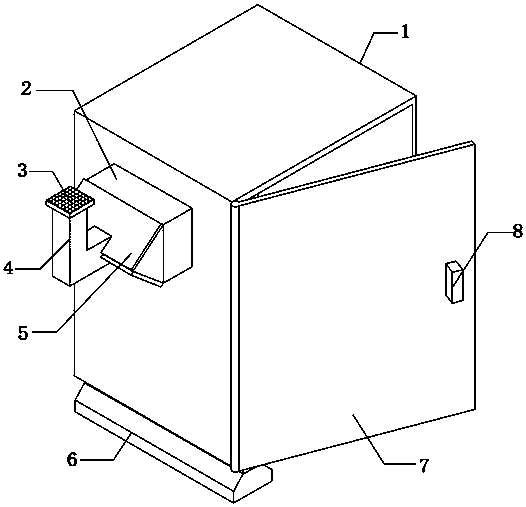
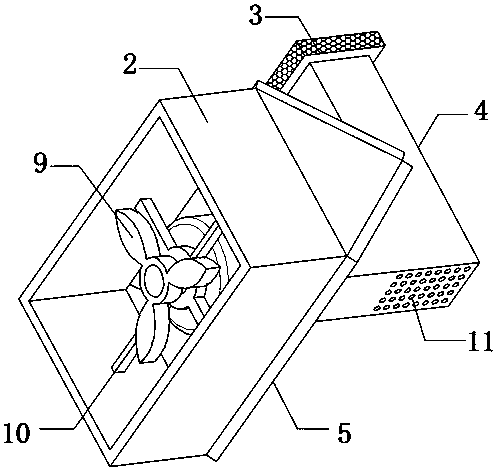
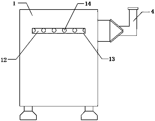
[0023] refer to Figure 1-3 , a power distribution cabinet, comprising a cabinet body 1, a through hole is opened on one side of the outer wall of the cabinet body 1, and a fixed frame 2 is fixedly connected to the outer wall of the through hole, and a sealing frame 5 is fixedly connected to the outer wall of the fixed frame 2, and the sealed The outer wall of the frame 5 is fixedly connected with a rain pipe 4, the top outer wall of the rain pipe 4 is fixedly connected with a dustproof plate 3, and the bottom outer wall of the rain pipe 4 is equidistantly provided with water holes 11. In the rain pipe 4, the dust-proof net 3 blocks litter and fallen leaves to prevent it from blocking the rain pipe 4, and at the same time, the water entering the rain pipe 4 falls through the water hole 11, and cannot enter the fixed frame 2 along the sealing frame 5 , and then cannot enter the cabinet 1, thereby improving the rainproof performance of the cabinet 1 and improving the service lif...

Embodiment 2

[0030] refer to Figure 1-4 , a power distribution cabinet, comprising a cabinet body 1, a through hole is opened on one side of the outer wall of the cabinet body 1, and a fixed frame 2 is fixedly connected to the outer wall of the through hole, and a sealing frame 5 is fixedly connected to the outer wall of the fixed frame 2, and the sealed The outer wall of the frame 5 is fixedly connected with a rain pipe 4, the top outer wall of the rain pipe 4 is fixedly connected with a dustproof plate 3, and the bottom outer wall of the rain pipe 4 is equidistantly provided with water holes 11. In the rain pipe 4, the dust-proof net 3 blocks litter and fallen leaves to prevent it from blocking the rain pipe 4, and at the same time, the water entering the rain pipe 4 falls through the water hole 11, and cannot enter the fixed frame 2 along the sealing frame 5 , and then cannot enter the cabinet 1, thereby improving the rainproof performance of the cabinet 1 and improving the service lif...


PUM


Abstract

The invention belongs to the technical field of electric power engineering, and particularly relates to a power distribution cabinet. In order to increase the heat dissipation function of an existingpower distribution cabinet, heat dissipation equipment is often installed on the cabinet body. Heat dissipation equipment is generally a heat dissipation fan. When the heat dissipation fan works, external air needs to be guided into the cabinet body, so that the heat dissipation fan and the cabinet body are communicated. Rainwater easily falls into the cabinet body along a communication point to influence equipment in the cabinet body, cause moisture of the equipment and affect the service life of the equipment in the cabinet body when it rains. According to the scheme, the power distributioncabinet comprises a cabinet body. According to the invention, a sealing plate, a rain guide pipe and water passing holes are arranged; in rainy days, rainwater enters the rain guide pipe, and a dust screen blocks dry branches and fallen leaves to prevent the dry branches and fallen leaves from blocking the rain guide pipe; water entering the rain guide pipe falls through the water passing holes, cannot enter a fixed frame along a sealing frame and then cannot enter the cabinet body; the rainproof performance of the cabinet body is improved; and the service life of the equipment in the cabinetbody is prolonged.

Description

technical field [0001] The invention relates to the technical field of electric power engineering, in particular to a power distribution cabinet. Background technique [0002] The power distribution cabinet (box) is divided into power distribution cabinet (box), lighting distribution cabinet (box), metering cabinet (box), and is the final equipment of the power distribution system; power distribution cabinet is the collective name of the motor control center; power distribution The cabinet is used in the occasions where the load is relatively scattered and there are few circuits; the motor control center is used in the occasions where the load is concentrated and there are many circuits. [0003] In order to increase the heat dissipation function of the existing power distribution cabinet, heat dissipation equipment is often installed on the cabinet body. The heat dissipation equipment is generally a heat dissipation fan. When the heat dissipation fan is working, it needs to...

Claims


Application Information

Patent Timeline
IPC IPC(8): H02B1/30H02B1/28H02B1/20H02B1/56
CPCH02B1/20H02B1/28H02B1/30H02B1/565
Inventor 徐明法包彦国
Owner 台州宏发输配电成套设备有限公司
Why Eureka
Try Eureka