

Cylinder hoisting equipment
A technology for hoisting equipment and cylinders, which is applied in hoisting devices, construction, excavation, etc., and can solve problems such as poor working environment for workers, poor ventilation at the bottom of shaft wells, and low construction efficiency in driving operations, etc.
- Summary
- Abstract
- Description
- Claims
- Application Information
AI Technical Summary
Problems solved by technology
Method used
Image

Examples
Embodiment 1
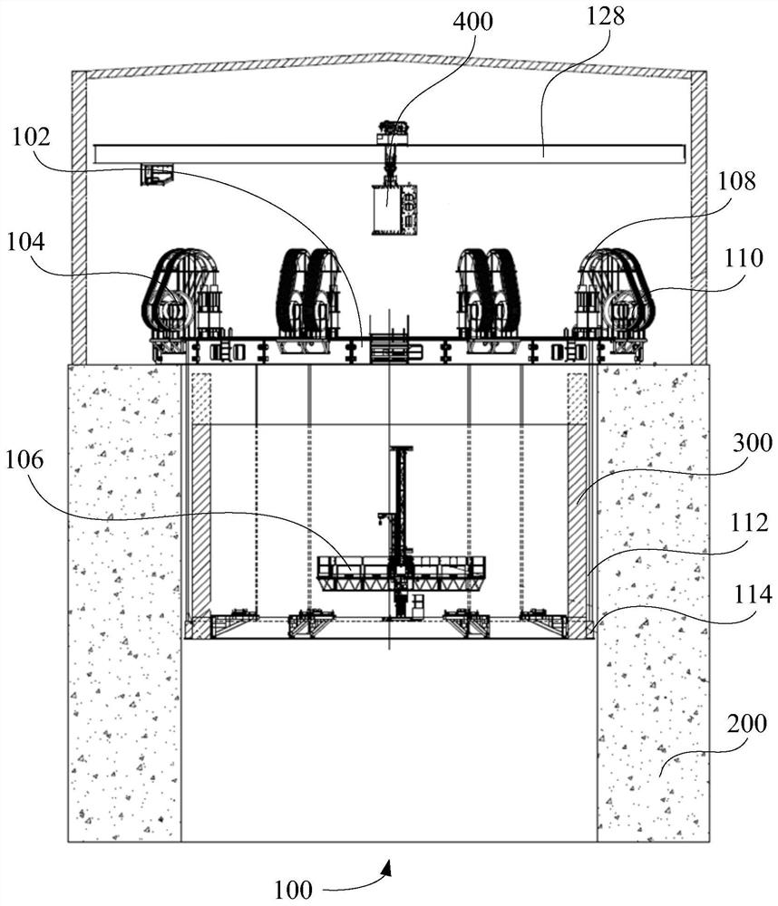
[0056] Such as figure 1 As shown, the first embodiment of the present invention proposes a cylinder hoisting device 100 , including: a carrying mechanism 102 , a lifting mechanism 104 and a lifting platform 106 .
[0057] Wherein, the lifting mechanism 104 is arranged on the supporting mechanism 102, and can drive the welded cylinder body 300 to rise and fall; the interior of the welded cylinder body 300 is provided with a lifting platform 106, and the lifting platform 106 can be lifted inside the welded cylinder body 300 to ensure the working The construction position of the personnel matches the welding area. Specifically, the welding area is located above the shaft 200, at ground level. That is to say, the cylinder hoisting device 100 proposed by the present invention can realize the welding operation of the staff on the ground, effectively improve the construction work environment of the staff, and improve the efficiency of construction work.
[0058] Specifically, the c...
Embodiment 2
[0065] Such as figure 1 As shown, the second embodiment of the present invention proposes a cylinder hoisting device 100 , including: a carrying mechanism 102 , a lifting mechanism 104 , a lifting platform 106 and a connecting seat 114 .
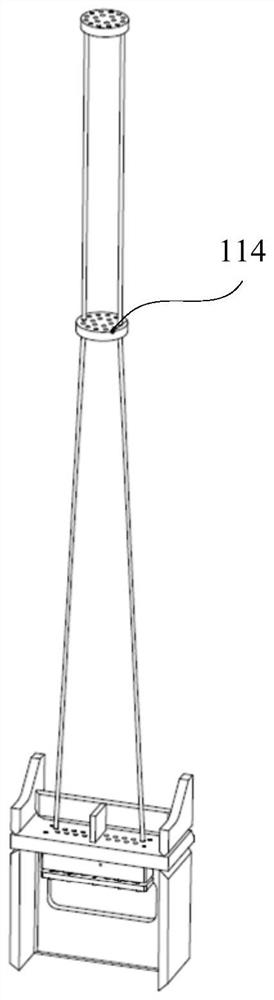
[0066] Wherein, the lifting mechanism 104 is arranged on the supporting mechanism 102, and can drive the welded cylinder body 300 to rise and fall; the interior of the welded cylinder body 300 is provided with a lifting platform 106, and the lifting platform 106 can be lifted inside the welded cylinder body 300 to ensure the working The construction position of the personnel matches the welding area; the connecting seat 114 is arranged at the bottom of the welded cylinder 300 , and the welded cylinder 300 is configured to be connected to the rope body 112 through the connecting seat 114 .
[0067] In this example, if figure 1 and figure 2 As shown, a connection seat 114 is provided at the bottom of the welded cylinder body 300 , and the r...
Embodiment 3
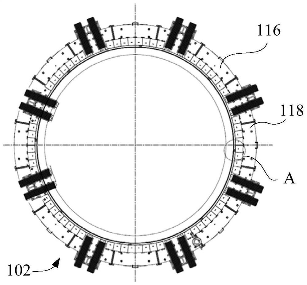
[0069] Such as figure 1 As shown, the third embodiment of the present invention proposes a cylinder hoisting device 100, including: a bearing mechanism 102, a lifting mechanism 104, a lifting platform 106 and a circular working platform (not shown in the figure).
[0070]Wherein, the lifting mechanism 104 is arranged on the supporting mechanism 102, and can drive the welded cylinder body 300 to rise and fall; the interior of the welded cylinder body 300 is provided with a lifting platform 106, and the lifting platform 106 can be lifted inside the welded cylinder body 300 to ensure the working The construction position of the personnel matches the welding area; the ring-shaped work platform can play a good role in positioning during the construction process.
[0071] In this embodiment, an annular working platform is set on the bearing mechanism 102, and the annular working platform is concentrically arranged with the wellhead of the vertical shaft 200, and the outer diameter o...
PUM
 Abstract
Description
Claims
Application Information