Novel treatment bed

A treatment bed, a new type of technology, applied in the direction of hospital beds, medical science, hospital equipment, etc., can solve problems such as inconvenience in operation, and achieve the effect of easy work and reduced labor intensity.

Active Publication Date: 2020-07-28
THE FIRST AFFILIATED HOSPITAL OF ARMY MEDICAL UNIV
View PDF12 Cites 2 Cited by
  • Summary
  • Abstract
  • Description
  • Claims
  • Application Information

AI Technical Summary

Problems solved by technology

[0003] The present invention intends to provide a new type of treatment bed to solve the inconvenient operation caused by lifting the limb with one hand and treating the wound with the other hand when the traditional Chinese medicine nurse debrides the limb of the patient in the prior art question

Method used


Image

  • Novel treatment bed
  • Novel treatment bed
  • Novel treatment bed

Examples


Embodiment 1

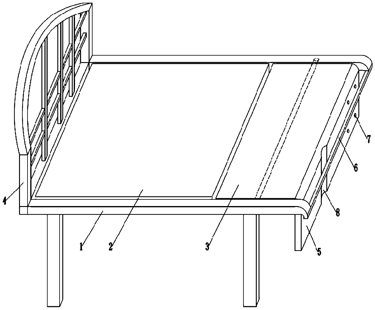
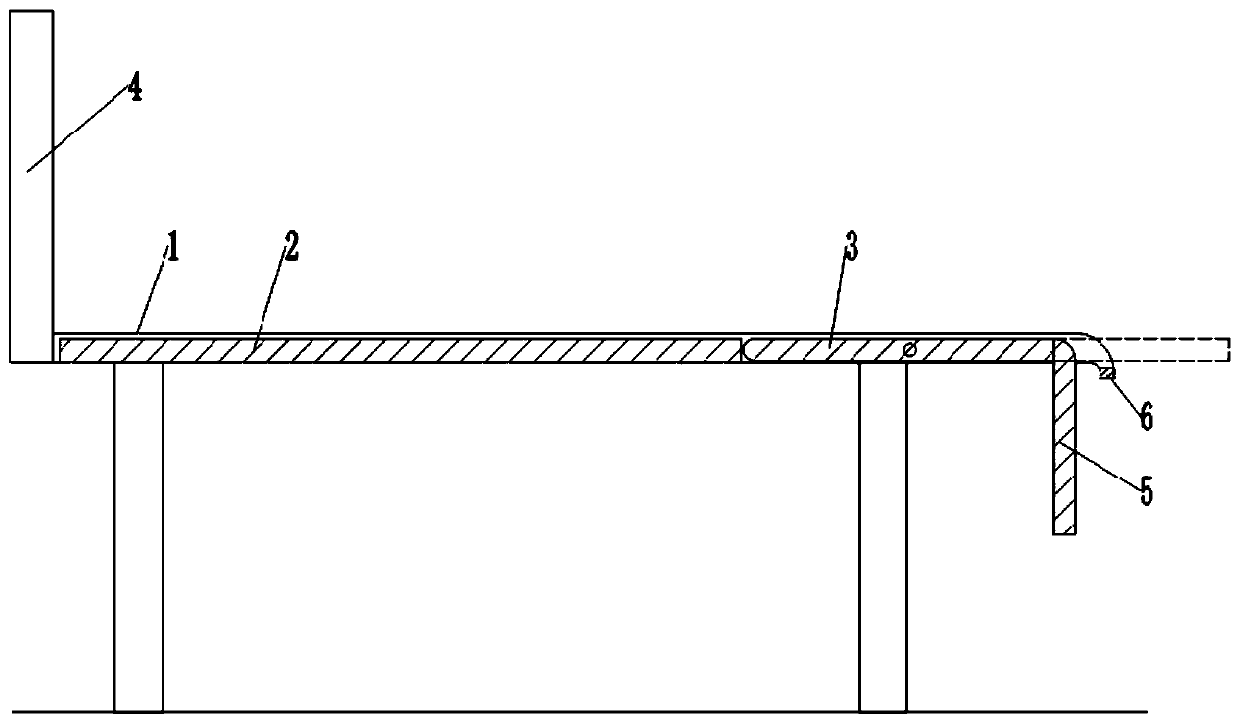
[0033] as attached figure 1 Shown: a new type of treatment bed, including a bracket 1 and a bed board, the left end of the bracket 1 is fixed with a backrest 4 by bolts; the bed board includes a fixed board 2 and a movable board 3, the fixed board 2 and the bracket 1 are fixed by bolts, and the movable board 3 The upper rotation is provided with a slide block, and the specific setting method is as follows: the movable plate 3 is clamped and fixedly provided with a pivot pin (the pivot pin is figure 1 The dotted line part in ), the two ends of the shaft pin are respectively provided with a slider ( figure 1 The slide block is not shown in the figure), the slide block is provided with a shaft hole, and the shaft pin can be inserted into the shaft hole and matched with the shaft hole clearance, so that the movable plate 3 and the slide block can rotate relatively. In the actual production process, it can also be A chute is set in the shaft hole on the slider, and a boss is clamp...

Embodiment 2

[0039] Such as Figure 4 , Figure 5 As shown, the difference between this embodiment and Embodiment 1 is that the lower side of the fixed plate 2 is detachably provided with a trash can 9, specifically, the lower side of the fixed plate 2 slides horizontally through a guide rail to be provided with an installation assembly, and the installation assembly includes a placement plate 10 and connecting rod 11, the head end of connecting rod 11 ( Figure 4 The upper end of the middle) is slidingly connected with the fixed plate 2, and the tail end of the connecting rod 11 ( Figure 4 middle lower end) and the placement plate 10 are fixed by bolts, and the placement plate 10 is provided with an accommodating groove for placing the garbage can 9, and the garbage can 9 is movably placed in the accommodating groove.

[0040] The right-hand clamping of placing plate 10 is fixedly provided with driving rod 12, and the free end of driving rod 12 ( Figure 4 upper end) and movable plate...

Embodiment 3

[0043] Such as Figure 6 As shown, the difference between the present embodiment and the second embodiment is that the upper cover 13 is detachably fixedly connected to the trash can 9, and the sliding connection is taken as an example for illustration here.

[0044] During specific use, after the cleaners clean the trash can 9, they don't need to rotate and fix the upper cover 13 on the trash can 9, but directly put the upper cover 13 on the trash can 9 or put it in other places;

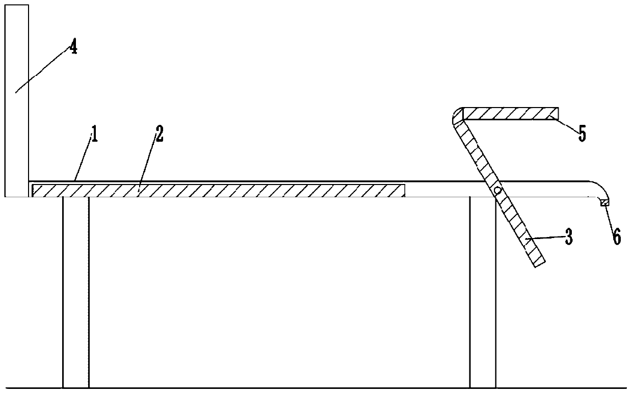
[0045] When the medical personnel perform debridement on the patient, a gap is formed between the movable plate 3 and the fixed plate 2 after being driven to rotate. Garbage is thrown in the trash can 9; After use, because the trash can 9 is located at the gap position between the movable plate 3 and the fixed plate 2 during use, it is also convenient for people to pass the opening to cover the upper cover 13 tightly; the trash can The loam cake 13 on the 9 is connected on the garbage can 9 by thr...


PUM


Abstract

The invention relates to the technical field of auxiliary medical equipment and discloses a novel treatment bed which comprises a support and a bed plate, the bed plate comprises a fixed plate and a movable plate, the fixed plate and the support are fixed, a sliding block is hinged to the movable plate and slidably connected with the support, one side of the movable plate can make contact with thefixed plate, and a supporting plate is hinged to the other side of the movable plate. By the adoption of the scheme, the technical problem that in the prior art, medical staff need to manually lift the limbs of a patient to treat wounds can be solved.

Description

technical field [0001] The invention relates to the technical field of auxiliary medical equipment, and specifically discloses a novel treatment bed. Background technique [0002] When a patient's limbs are injured, especially in the case of a leg injury, the situation of the patient's limbs is generally reduced as much as possible to avoid secondary injuries caused by the wound being pulled. Therefore, when the medical staff changes the dressing of the patient or cleans the affected area in the dressing room, the patient usually lies on the treatment bed to rest, and the medical staff lifts the patient's leg to a certain height with one hand, so that the leg is in line with the bed surface. Separated, the other hand removes the original bandage, etc., cleans the wound, and then wraps the new medicine and bandage on the patient's leg, so the existing treatment method is very inconvenient to operate; moreover, in the ward The table is generally set at the bedside of the trea...

Claims


Application Information

Patent Timeline
Patent Type & Authority Applications(China)
IPC IPC(8): A61G7/015A61G7/05A61G7/075
CPCA61G7/015A61G7/05A61G7/0506A61G7/0755
Inventor 丁丽娜王红霞
Owner THE FIRST AFFILIATED HOSPITAL OF ARMY MEDICAL UNIV
Why Eureka
Try Eureka