A capacitor discharge device

A technology of a discharge device and a capacitor, applied in the field of capacitors, can solve the problems of electric shock accidents, poor contact between the discharge conductor and the capacitor contacts, and excessive physical exertion of operators, and achieves the effect of saving physical strength.

Active Publication Date: 2021-09-07
HUIZHOU POWER SUPPLY BUREAU OF GUANGDONG POWER GRID CO LTD
View PDF4 Cites 0 Cited by
  • Summary
  • Abstract
  • Description
  • Claims
  • Application Information

AI Technical Summary

Problems solved by technology

[0004] However, when using these discharge tools, since the discharge conductor is pressed against the contact of the capacitor by manpower, it will cause the operator to consume more physical strength, and the discharge conductor often slides on the capacitor contact, etc., resulting in discharge Poor contact between the conductor and the capacitor contact, it is difficult to discharge the residual charge in the capacitor, which may cause electric shock accidents

Method used


Image

  • A capacitor discharge device
  • A capacitor discharge device
  • A capacitor discharge device

Examples


Embodiment 1

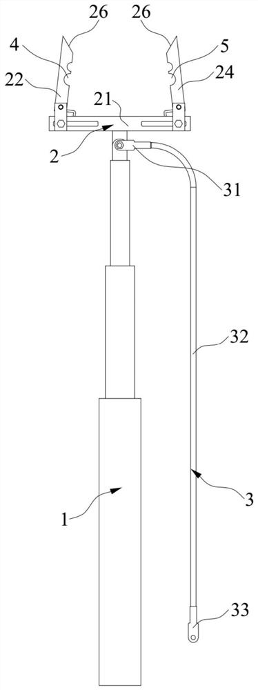
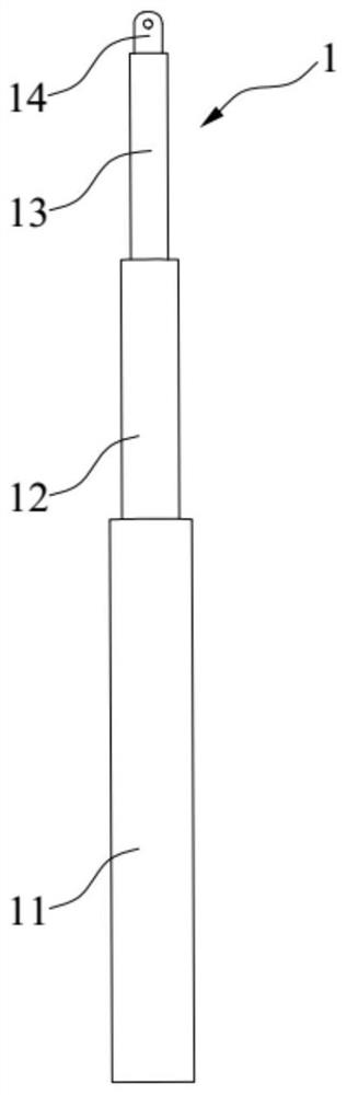
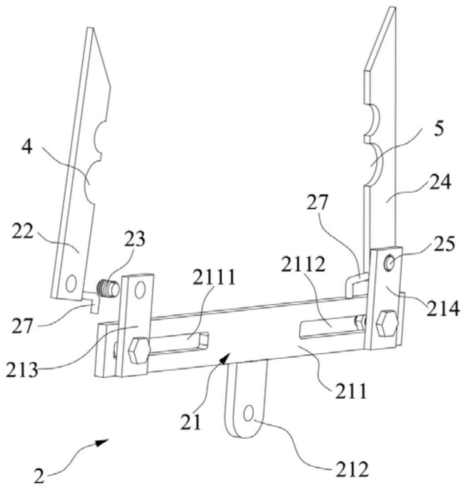
[0037] This embodiment provides a capacitor discharge device. Such as figure 1 As shown, the capacitor discharge device includes an insulating rod 1 , a discharge conductor 2 and a ground wire 3 . The discharge conductor 2 is arranged at one end of the insulating rod 1 . The discharge conductor 2 includes a fixing frame 21 and two elastic arms connected with the fixing frame 21 . The fixing frame 21 is connected with the insulating rod 1 . The first end of the ground wire 3 is connected to the fixing frame 21, and the second end is used for grounding. The two elastic arms are relatively spaced apart, and when opened, the positive contact and the negative contact of the capacitor to be discharged can be inserted from the outside of the contact of the capacitor to be discharged at the same time, and when closed, they are respectively pressed against the outside of the positive contact and the negative contact. The outer side of the contact can ensure that the discharge conduct...

Embodiment 2

[0059] This embodiment provides a capacitor discharge device, which has roughly the same structure as the capacitor discharge device provided in Embodiment 1, the only difference being that the two elastic arms are configured to be able to extend into the positive contact and the negative contact when they are closed between them, and press against the inner side of the positive contact and the inner side of the negative contact of the capacitor to be discharged respectively when opened. According to this arrangement, the two elastic arms can also ensure that the discharge conductor 2 is in close contact with the positive contact and the negative contact, thereby greatly saving the physical strength of the operating personnel. It can be understood that the inner side of the positive contact and the inner side of the negative contact refer to opposite sides of the positive contact and the negative contact.

[0060]At the same time, on the abutting side of the elastic arm and th...


PUM


Abstract

The invention discloses a capacitor discharge device and relates to the technical field of capacitors. It consists of insulating rods, discharge conductors and grounding conductors. The discharge conductor includes a fixed frame and two elastic arms connected with the fixed frame, the fixed frame is connected with one end of the insulating rod, and the two elastic arms are arranged at intervals relative to each other. The two elastic arms are configured to simultaneously cover the positive and negative contacts of the capacitor to be discharged when they are opened, and respectively press against the outside of the positive and negative contacts when they are closed; or are configured to protrude into the Between the positive pole contact and the negative pole contact, and press against the inner sides of the positive pole contact and the negative pole contact respectively when opened. The contact side of the elastic arm and the contact of the capacitor is also respectively provided with a first socket capable of engaging with the positive electrode contact and a second bayonet socket capable of engaging with the negative electrode contact. When discharging through the capacitor discharge device, the physical strength of the operating personnel can be greatly saved, good contact with the capacitor contacts can be ensured, and residual charges can be exhausted.

Description

technical field [0001] The invention relates to the technical field of capacitors, in particular to a capacitor discharge device. Background technique [0002] When the parallel capacitor bank disconnects the circuit breaker and disconnects from the grid, because the moment of disconnection is at a high voltage moment, there is still a lot of charge on the capacitor bank, and the voltage at both ends of the capacitor bank is very high. For this reason, discharge coils are installed at both ends of the capacitor bank. After the capacitor bank is disconnected from the power supply, the residual voltage on the capacitor bank can be reduced to 50V or below within 5 seconds. Even so, however, residual charge remains in the capacitor bank. Therefore, in order to prevent the residual charge from threatening personal safety, the power industry stipulates that each capacitor in the capacitor bank should be discharged several times one by one before working on the capacitor bank or e...

Claims


Application Information

Patent Timeline
Patent Type & Authority Patents(China)
IPC IPC(8): H01R11/11H01R4/48
CPCH01R4/48H01R11/11
Inventor 龚演平王铁柱张斌斌郭振锋傅龙伟汪东
Owner HUIZHOU POWER SUPPLY BUREAU OF GUANGDONG POWER GRID CO LTD
Why Eureka
Try Eureka