Body cavity drainage device with tube replacing component

A technology for tube components and body cavities, applied in the field of body cavity drainage devices, can solve the problems of difficult insertion of guide wires, easy displacement or slipping out, time-consuming and labor-intensive problems, and achieve good fixation, increased fixed area, and safe and reliable use

Pending Publication Date: 2020-09-15
PEKING UNIV SHENZHEN HOSPITAL
View PDF0 Cites 0 Cited by
  • Summary
  • Abstract
  • Description
  • Claims
  • Application Information

AI Technical Summary

Problems solved by technology

[0004] Specifically, on the one hand, the tube body is elongated. After the tube body is inserted into the patient's body cavity, the front end of the tube body is not very fixed, so that it is easy to shift or slip out when it is slightly pulled. On the other hand, when the tube body of the corresponding drainage tube is blocked by fluid in the body or when it has been used for a specified period of time, it needs to be replaced. The traditional tube replacement operation is generally to use a guide wire to extend into the patient's body cavity along the corresponding tube body Drainage site, then pull out the corresponding tube body and insert a new drainage tube body to be replaced along the corresponding guide wire
Related tube replacement operations are very common. However, when the tube body of the corresponding drainage tube is blocked, the guide wire used is difficult to insert. At this time, it is necessary for the medical staff to slowly move the guide wire back and forth until the corresponding drainage tube is found. The tube body of the tube is not completely blocked, so that the operation of inserting the guide wire is time-consuming and laborious. When the tube body of the corresponding drainage tube is completely blocked by fluid in the body, it needs to be re-diagnosed under ultrasound and other imaging. Putting tubes on patients, in this way, will increase medical costs, and simultaneously increase the workload of medical staff and increase the discomfort of patients such as pain

Method used


Image

  • Body cavity drainage device with tube replacing component
  • Body cavity drainage device with tube replacing component
  • Body cavity drainage device with tube replacing component

Examples


Embodiment Construction

[0054] The technical solution of the present invention will be described in detail below in conjunction with the accompanying drawings and specific embodiments, so as to understand the essence of the present invention more clearly and intuitively.

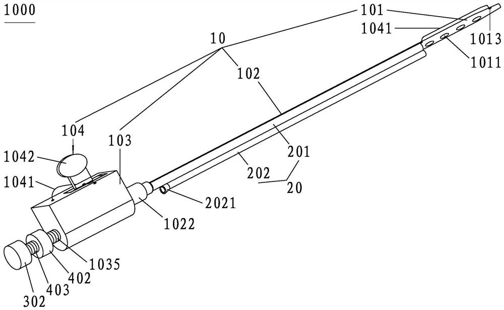
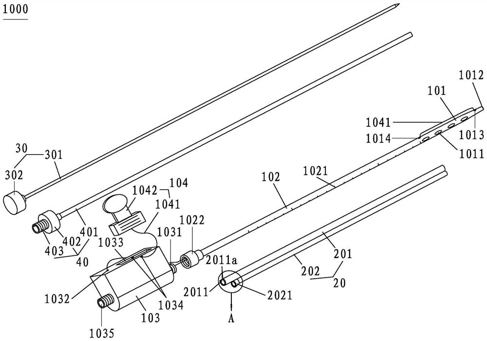
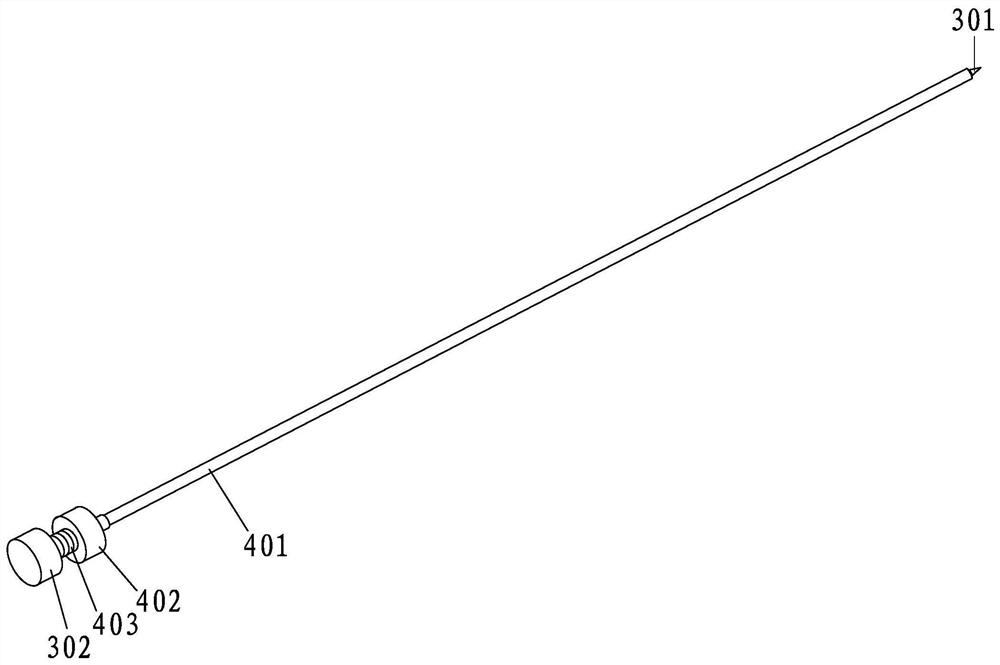
[0055] figure 1 It is a schematic diagram of the overall structure of the body cavity drainage device with tube replacement components of the present invention; figure 2 It is an exploded view of the body cavity drainage device with tube changing components of the present invention; image 3 It is a schematic diagram of the overall structure of the connection between the guide pin and the guide sleeve in this embodiment; Figure 4 In this embodiment, it is a diagram of the use state when the head of the front end of the drainage tube is rolled into a ring; Figure 5 In this embodiment, the auxiliary component for replacing the drainage tube is connected to the outside of the drainage tube whose front end tube head is rolled into...


PUM


Abstract

The invention discloses a body cavity drainage device with a tube replacing component. The device comprises a drainage tube and a drainage tube replacement auxiliary component, wherein the drainage tube comprises a tube head, a tube body, a tube base and a tube head pulling and rolling component. The drainage tube replacement auxiliary component comprises a sleeve with the length equal to that ofthe tube body and a guide tube connected with the sleeve into a whole. The inner diameter of the sleeve is slightly greater than the outer diameter of the tube body; a notch groove is formed in the outer wall of the sleeve in the length direction; the body cavity drainage device has the effects that the drainage tube replacement auxiliary component is disassembled and taken off when a patient is cathetered; after catheterization, the tube head pulling and rolling component is manually controlled, the tube head of the drainage tube can be driven to be rolled into a ring, therefore, the drainagedevice can be well stumbled by body cavity tissues of a body cavity of a patient needing external drainage of hydrops, and is not prone to displacement and sliding out, and is well fixed, and when the drainage tube replacement auxiliary component is used for tube replacement operation, the tube replacement speed is high, time and labor are saved during operation, the workload of medical staff canbe greatly relieved, the medical cost of a patient is reduced, and discomfort such as pain of the patient is relieved.

Description

technical field [0001] The invention relates to the technical field of medical care products, in particular to a body cavity drainage device with a tube changing member. Background technique [0002] In major hospitals, a built-in drainage tube is often inserted into the patient's body cavity for external drainage of body cavity fluid, such as peritoneal effusion drainage and pleural effusion drainage. [0003] Commonly used drainage tubes mainly include a tube body and a socket connected to the outside of the corresponding tube for external drainage. Although drainage tubes with corresponding structures are widely used, they still have certain defects and deficiencies; [0004] Specifically, on the one hand, the tube body is elongated. After the tube body is inserted into the patient's body cavity, the front end of the tube body is not very fixed, so that it is easy to shift or slip out when it is slightly pulled. On the other hand, when the tube body of the corresponding ...

Claims


Application Information

Patent Timeline
Patent Type & Authority Applications(China)
IPC IPC(8): A61M25/00A61M25/01A61B17/34A61M25/04
CPCA61B17/3403A61B17/3415A61B2017/3413A61M25/0021A61M25/0043A61M25/0169A61M25/04A61M2025/0008
Inventor 钟洁愉
Owner PEKING UNIV SHENZHEN HOSPITAL
Why Eureka
Try Eureka