Automatic riveting module for traffic sign aluminum alloy bottom plate

A riveting die and aluminum alloy technology, which is applied in the field of automatic riveting modules for aluminum alloy base plates of traffic signs, can solve the problems of increasing the production and forming time of sign plates, the separation and damage of sign plate plates, and the relative stress conflict of plates, etc., to achieve effective riveting process. High efficiency, reduced labor costs, and high riveting precision

Inactive Publication Date: 2020-09-29
广州市公路实业发展有限公司 +1
View PDF0 Cites 0 Cited by
  • Summary
  • Abstract
  • Description
  • Claims
  • Application Information

AI Technical Summary

Problems solved by technology

[0002] With the rapid development of basic equipment such as roads and bridges, other facilities such as billboards and traffic signs around the road are gradually improving. The existing billboards and traffic signs are all types of signs, usually two or more There are multiple pieces, and the plates need to be connected together through the cooperation of reinforcing ribs and aluminum profiles. The existing riveting operations are mostly riveted by manual riveting guns. The signboard is large in size, and there are many positions that need to be riveted. The riveting pressure is consistent. It is necessary to manually perform riveting operations repeatedly, which increases the labor intensity of the personnel and increases the production and molding time of the signs. At the same time, when the riveting operation is performed manually, the rivet position is difficult to maintain uniformity, and riveting errors are prone to occur, or the gap between the plates caused by large position deviations The relative stress conflicts between the riveted signboards are prone to plate separation and damage after riveting. However, riveting guns are used for riveting in the market, which is time-consuming and laborious, and the riveting efficiency is low, and riveting failures are prone to occur.

Method used


Image

  • Automatic riveting module for traffic sign aluminum alloy bottom plate
  • Automatic riveting module for traffic sign aluminum alloy bottom plate
  • Automatic riveting module for traffic sign aluminum alloy bottom plate

Examples


Embodiment Construction

[0043] The present invention will be described in detail below in conjunction with the accompanying drawings and specific embodiments, and the present invention will be described in detail below in conjunction with the accompanying drawings and specific embodiments. To explain the present invention, but not as a limitation of the present invention.

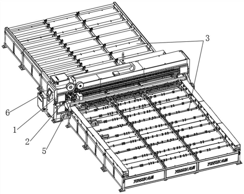
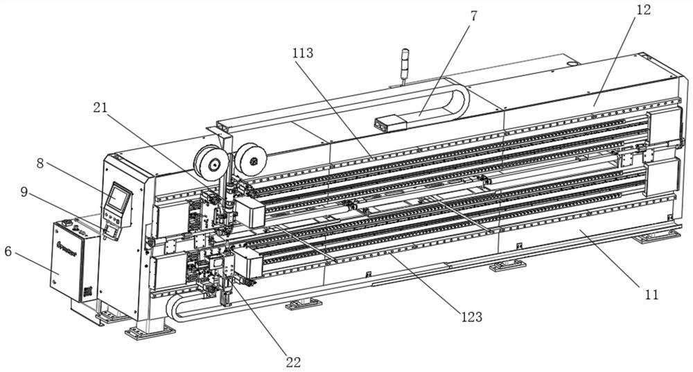
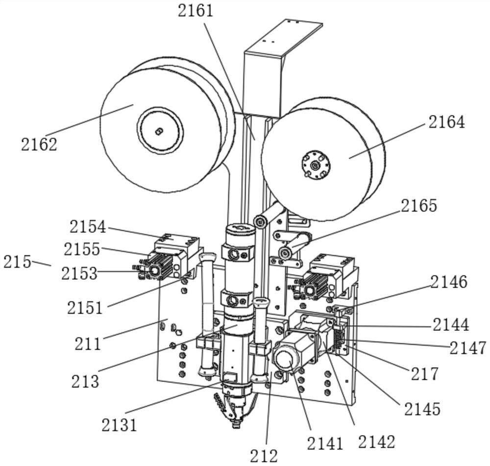
[0044] like Figure 1 to Figure 21 As shown in the figure, an automatic riveting module for the aluminum alloy bottom plate of a traffic sign, including:

[0045] A gantry support 1, the gantry support 1 comprising a first gantry 11 and a second gantry 12; the second gantry 12 is fixedly mounted on the top surface of the first gantry 11;

[0046] A riveting mechanism 2, the riveting mechanism 2 includes a self-propelled upper riveting module 21 and a self-propelled lower riveting module 22; the self-propelled upper riveting module 21 is movably mounted on the second gantry 12; The self-propelled lower riveting module 22 is movab...


PUM


Abstract

The invention discloses an automatic riveting module for a traffic sign aluminum alloy bottom plate. The automatic riveting module comprises a gantry support and a riveting mechanism. The gantry support comprises a first gantry and a second gantry. The second gantry is fixedly erected on the top face of the first gantry. The riveting mechanism comprises a self-propelled upper riveting module and aself-propelled lower riveting module. The self-propelled upper riveting module is movably mounted on the second gantry. The self-propelled lower riveting module is movably mounted on the first gantry. The self-propelled upper riveting module and the self-propelled lower riveting module synchronously move to carry out fixed-point riveting on a workpiece. The automatic riveting module is high in automation degree, high in production efficiency, capable of automatically riveting a traffic sign, high in riveting precision and good in riveting quality.

Description

technical field [0001] The invention relates to the technical field of riveting, in particular to an automatic riveting module for an aluminum alloy bottom plate of a traffic sign. Background technique [0002] With the rapid development of basic equipment such as roads and bridges, other facilities such as billboards and traffic signs around the road are gradually improving. The existing billboards and traffic signs are all types of signs, usually two or more There are multiple pieces, and the plates need to be connected together through the cooperation of reinforcing ribs and aluminum profiles. The existing riveting operations are mostly riveted by manual riveting guns. The signboard is large in size, and there are many positions that need to be riveted. The riveting pressure is consistent. It is necessary to manually perform riveting operations repeatedly, which increases the labor intensity of the personnel and increases the production and molding time of the signs. At t...

Claims


Application Information

Patent Timeline
Patent Type & Authority Applications(China)
IPC IPC(8): B21J15/14B21J15/38
CPCB21J15/14B21J15/38
Inventor 叶振华肖华彪张钦展金渊周群辉曾加亮
Owner 广州市公路实业发展有限公司
Why Eureka
Try Eureka