Bearing retainer convenient to disassemble and assemble

A technology for easy disassembly and assembly of bearing cages, which is applied to bearing components, shafts and bearings, mechanical equipment, etc., and can solve problems such as difficult removal of bearing cages

Active Publication Date: 2020-10-23
苏州汇智精保持架科技有限公司
View PDF14 Cites 3 Cited by
  • Summary
  • Abstract
  • Description
  • Claims
  • Application Information

AI Technical Summary

Problems solved by technology

[0004] The purpose of the present invention is to provide a bearing cage that is easy to disassemble in order to solve the problem that the existing bearing cage is difficult to remove after being installed and fixed.

Method used


Image

  • Bearing retainer convenient to disassemble and assemble
  • Bearing retainer convenient to disassemble and assemble
  • Bearing retainer convenient to disassemble and assemble

Examples


Embodiment 1

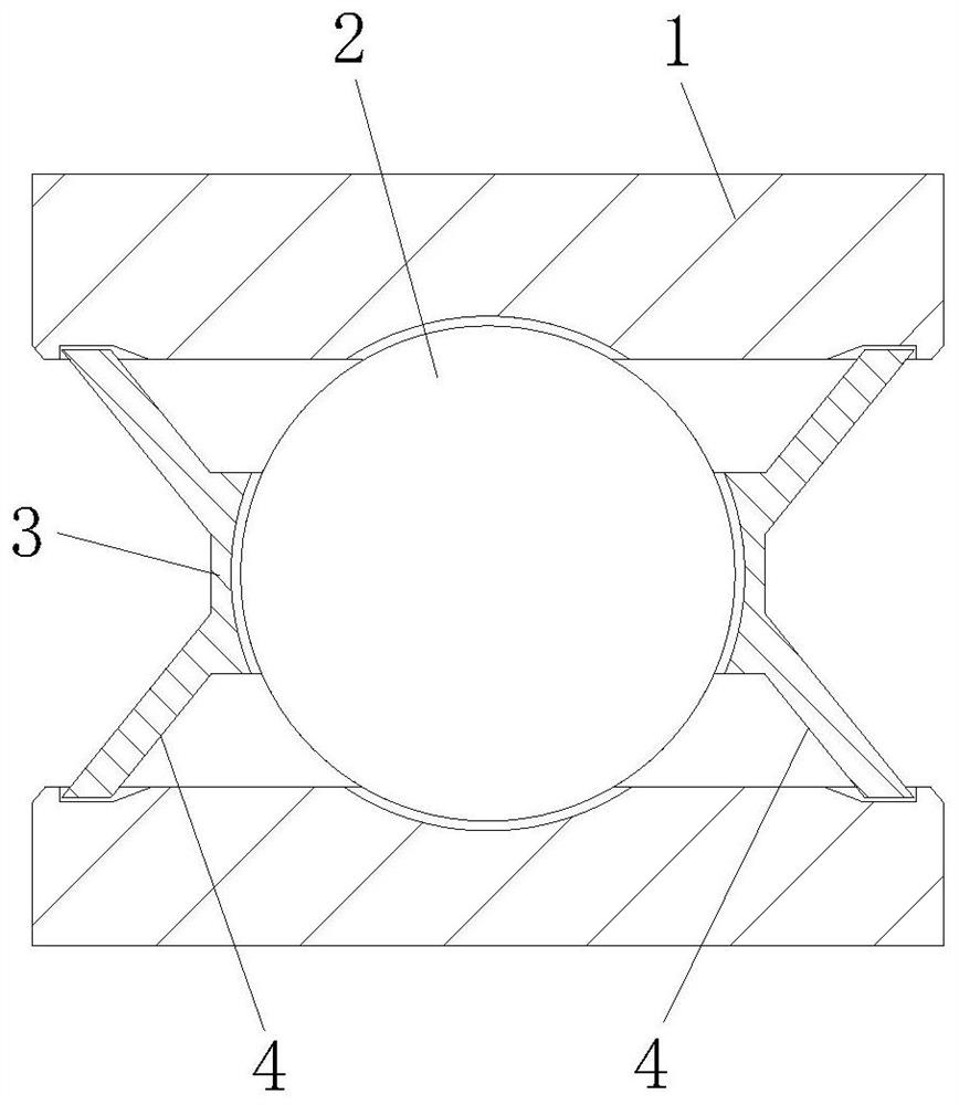
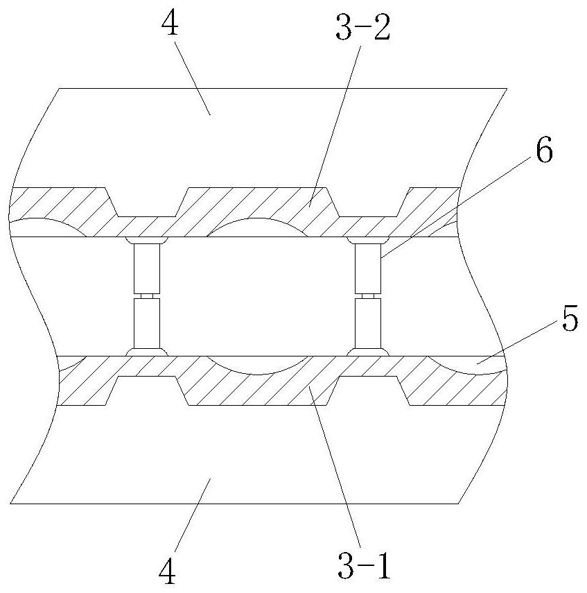
[0028] Example 1, please refer to Figure 1~3 , a bearing cage that is easy to disassemble and assemble, including a cage body 3 that surrounds the balls 2 laterally, and a flying plate 4 that reaches the shaft frame 1 is integrally formed on the cage body 3, and the flying plate 4 is used as a plugging shaft frame 1 and The sealing setting between the balls 2 is used to prevent foreign matter such as dust from entering the balls 2 and affecting the normal rotation of the balls 2, thereby affecting the overall service life of the bearing. Considering the friction between the fly plate 4 and the axle frame 1, Therefore, it is recommended that the flying plate 4 be made of nitrile rubber, and be fixed with the metal cage body 3 by embossing. The cage body 3 is provided with an arc-shaped groove 5 at the position close to the ball 2 for contact with the ball 2. Close to each other to facilitate the rolling of the ball 2;

[0029] The cage body 3 includes a front frame body 3-1 a...

Embodiment 2

[0030] Example 2, please refer to Figure 1~4 , a bearing cage that is easy to disassemble and assemble, including a cage body 3 that surrounds the balls 2 laterally, and a flying plate 4 that reaches the shaft frame 1 is integrally formed on the cage body 3, and the flying plate 4 is used as a plugging shaft frame 1 and The sealing setting between the balls 2 is used to prevent foreign matter such as dust from entering the balls 2 and affecting the normal rotation of the balls 2, thereby affecting the overall service life of the bearing. Considering the friction between the fly plate 4 and the axle frame 1, Therefore, it is recommended that the flying plate 4 be made of nitrile rubber, and be fixed with the metal cage body 3 by embossing. The cage body 3 is provided with an arc-shaped groove 5 at the position close to the ball 2 for contact with the ball 2. Close to each other to facilitate the rolling of the ball 2;

[0031] The cage body 3 includes a front frame body 3-1 a...

Embodiment 3

[0034] Embodiment three, please refer to Figure 1~2 and 5-6, a bearing cage that is easy to disassemble and assemble, including a cage body 3 that surrounds the balls 2 laterally, and a flying plate 4 that reaches the shaft frame 1 is integrally formed on the cage body 3, and the flying plate 4 is used as a plug The seal between the shaft frame 1 and the ball 2 is used to prevent foreign matter such as dust from entering the ball 2 and affecting the normal rotation of the ball 2, thereby affecting the overall service life of the bearing. Considering the fly plate 4 and the shaft frame 1 friction, so the flying plate 4 is recommended to be made of nitrile rubber, which is fixed with the metal cage body 3 by embossing. The cage body 3 is provided with an arc-shaped groove 5 at the position close to the ball 2. Because it is close to the ball 2, it is convenient for the ball 2 to roll;

[0035] The cage body 3 includes a front frame body 3-1 and a rear frame body 3-2 located on...


PUM


Abstract

The invention discloses a bearing retainer convenient to disassemble and assemble. The bearing retainer convenient to disassemble and assemble comprises retainer bodies transversely surrounding balls,wherein flying plates which are propped against a shaft bracket is integrally formed on the retainer bodies, arc-shaped grooves are formed in the positions, attached to the balls, of the retainer bodies, the retainer bodies comprises front frame bodies and rear frame bodies which are positioned on the front sides and the rear sides of the balls, the front frame bodies and the rear frame bodies between the adjacent balls are fixedly connected through limiting columns, the limiting columns comprises upper column bodies which are welded and fixed on the rear frame bodies and lower column bodieswhich are welded and fixed on the front frame bodies, hole grooves are formed in the upper column bodies, convex columns are welded on the upper tops of the lower column bodies and extend into the hole grooves, limiting grooves are formed in the upper column bodies on the left sides and the right sides of the hole grooves, and steel balls are placed in the limiting grooves. According to the bearing retainer convenient to disassemble and assemble, the flying plates made of rubber are integrally arranged with the retainer bodies, the flying plates are utilized to seal the inner sides of the balls, so that dust is prevented from entering, and the trouble of mounting a bearing oil seal in the later period is avoided. The flying plates and the retainer bodies are integrally formed, so that machining is quicker.

Description

technical field [0001] The invention belongs to the technical field of bearing equipment, in particular to a bearing cage which is convenient for disassembly and assembly. Background technique [0002] Bearings are an important part of contemporary mechanical equipment. Its main function is to support the mechanical rotating body, reduce the friction coefficient during its movement, and ensure its rotation accuracy. The bearing cage (that is, the bearing cage, also known as the bearing cage) refers to partially wrapping all or part of the rolling body , and the bearing parts that move with it, to isolate the rolling elements, and usually guide the rolling elements and keep them in the bearing. [0003] When the bearing is working, especially when the load is complex and rotates at high speed, the cage has to bear a lot of centrifugal force, shock and vibration, there is a large sliding friction between the cage and the rolling elements, and a lot of heat is generated. The ...

Claims


Application Information

Patent Timeline
Patent Type & Authority Applications(China)
IPC IPC(8): F16C33/38
CPCF16C33/38
Inventor 韩卫冬王世俊
Owner 苏州汇智精保持架科技有限公司
Why Eureka
Try Eureka