Electroplating process

A technology of electroplating process and electroplating device, which is applied in the direction of electrolysis process and electrolysis components, etc., can solve the problems of low electroplating efficiency of hollow column parts, achieve good effect and facilitate washing

Inactive Publication Date: 2020-11-03
冯玉武
View PDF1 Cites 2 Cited by
  • Summary
  • Abstract
  • Description
  • Claims
  • Application Information

AI Technical Summary

Problems solved by technology

At the same time, a film in the present invention can be reused many times, which can save costs to the greatest extent and reduce environmental pollution; but this process has low electroplating efficiency for hollow column parts

Method used


Image

  • Electroplating process
  • Electroplating process
  • Electroplating process

Examples


specific Embodiment approach 1

[0036] As shown in the figure, an electroplating process includes the following steps:

[0037] Step 1: placing the tube to be electroplated in the electroplating device for rinsing;

[0038] Step 2: acid-activating the tube;

[0039] Step 3: washing the tube;

[0040] Step 4: Copper-plating the tube;

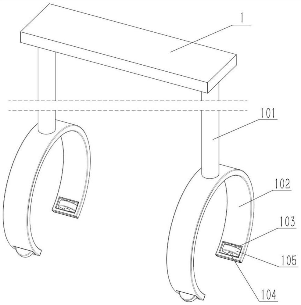
[0041] The above-mentioned electroplating process also includes an electroplating device, which includes a flat plate 1, an extension rod 101, a ring body 102, a wheel notch 103, a shaft I 104 and a wheel 105, and the left and right sides of the lower end of the flat plate 1 are fixedly connected with an extension Rod 101, the lower ends of two extension rods 101 are all affixed with a ring body 102, and the front and rear sides of each ring body 102 lower side are all provided with a wheel notch 103, all affixed on each ring body 102 Two shafts I 104 and four shafts I 104 are respectively located in the four wheel notches 103 , and each shaft I 104 is rotatably connected to...

specific Embodiment approach 2

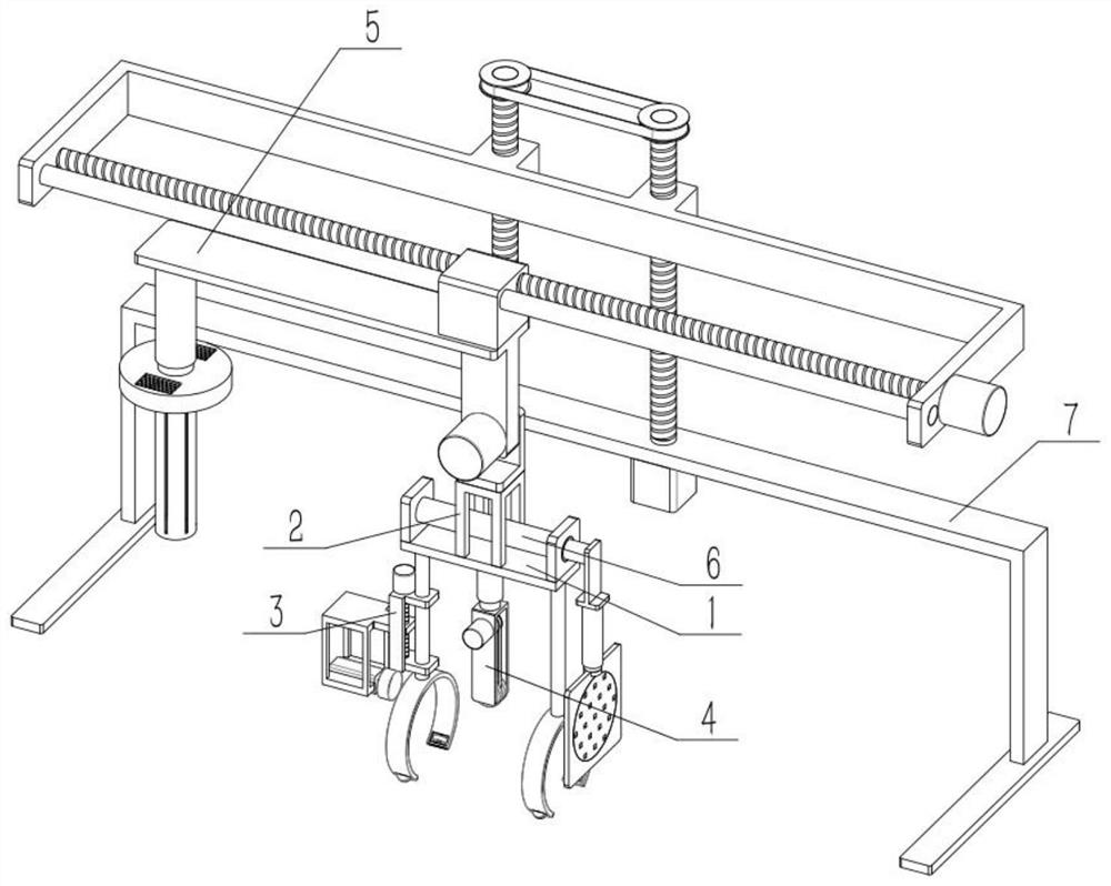
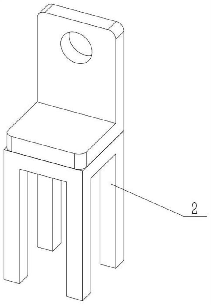
[0043] As shown in the figure, the electroplating device also includes an intermediate connecting seat 2, a combined base 5 and a motor IV501, the intermediate connecting base 2 is fixedly connected to the middle part of the upper end of the plate 1, and the lower side of the right end of the combined base 5 is fixedly connected to the motor IV501, and the motor IV501 The output shaft passes through from the back to the front and is rotatably connected to the combination seat 5, and the upper side of the intermediate seat 2 is fixedly connected to the output shaft of the motor IV 501. Start the motor Ⅳ501, the output shaft of the motor Ⅳ501 drives the middle connecting seat 2 to rotate, and the middle connecting seat 2 drives the plate 1 to rotate around the axis of the output shaft of the motor Ⅳ501. , which in turn changes the part from landscape orientation to portrait orientation.

specific Embodiment approach 3

[0045]As shown in the figure, the electroplating device also includes an electric push rod III6, a support plate 601, a board seat 602, an electric push rod IV603, a supporting plate 604, and a turntable 605. The electric push rod III6 is fixed to the support plate 601, and the support plate 601 is fixed Connected to the upper end of the plate 1, the board base 602 is fixed to the movable end of the electric push rod III6, the lower end of the board base 602 is fixed to the electric push rod IV 603, and the movable end of the electric push rod IV 603 is fixed to the supporting plate 604, and the supporting plate 604 Turn the connection dial 605 . Start the electric push rod Ⅲ6, the electric push rod Ⅲ6 is used to move the turntable 605 left and right, start the electric push rod Ⅳ603, and the electric push rod Ⅳ603 is used to move the turntable 605 up and down, so that the turntable 605 is adjusted to the right side of the part, so that the part After the right end is attached...


PUM


Abstract

The invention relates to electroplating, in particular to an electroplating process. The electroplating process comprises the following steps that 1, a to-be-electroplated tubular object is placed inan electroplating device to be flushed; 2, acid activation is carried out on the tubular object; 3, the tubular object is flushed; and fourthly, the tubular object is subjected to copper plating. An over-deep solution is not needed during transverse placement and soaking; and during longitudinal placement, a friction wheel I rotates to enable a longitudinally-placed part to rotate, the part makescontact with a rotary disc, the rotary disc also rotates along with the part, the rotary disc enables the part to rotate more easily during longitudinal placement, and then high-frequency flushing during electroplating is facilitated.

Description

technical field [0001] The present invention relates to electroplating, more specifically an electroplating process. Background technique [0002] For example, the publication number is CN102154668A, a mask electroplating process for printed circuit boards. The electroplating process includes the following steps: A, drilling: drilling out mechanical holes and via holes as required on the circuit board substrate; B, sticking film: after drilling The insulating film of the drilled hole is pasted on the circuit board substrate of the hole; C, copper plating: thicken the electroplating of the via hole; D, peeling off the film: peel off the insulating film attached to the circuit board substrate; E, the circuit plate for post-processing. The invention has a simple process, can greatly save metal materials such as copper and tin, reduce the consumption of precious metals, reduce the use of chemicals, reduce pollution, and is a printed circuit board mask exposed hole electroplatin...

Claims


Application Information

Patent Timeline
Patent Type & Authority Applications(China)
IPC IPC(8): C25D3/38C25D5/34C25D7/04C25D17/16
CPCC25D3/38C25D5/34C25D7/04C25D17/16
Inventor 冯玉武
Owner 冯玉武
Why Eureka
Try Eureka