Electric connector

A technology of electrical connectors and connectors, applied in the direction of conductive connection, connection, fixed connection, etc., can solve the problems of increased complexity of welding process, easy limitation of cable size, poor connection stability, etc., to achieve increased connection stability The effects of reliability, reduction of welding cost, and increase in selectivity

Active Publication Date: 2020-11-27
DONGGUAN LUXSHARE TECH CO LTD
View PDF4 Cites 0 Cited by
  • Summary
  • Abstract
  • Description
  • Claims
  • Application Information

AI Technical Summary

Problems solved by technology

[0003] The embodiment of the present application provides an electrical connector, which solves the problem that the current cables are directly welded on the terminals of the connector. Not only is the connection between the cables and the terminals not stable, but the size of the cables is easily restricted, which leads to a problem in the welding process. The complexity increases, which in turn increases the overall welding cost

Method used


Image

  • Electric connector
  • Electric connector
  • Electric connector

Examples


Embodiment Construction

[0022] The following will clearly and completely describe the technical solutions in the embodiments of the present application with reference to the drawings in the embodiments of the present application. Obviously, the described embodiments are part of the embodiments of the present application, not all of them. Based on the embodiments in this application, all other embodiments obtained by persons of ordinary skill in the art without creative efforts fall within the protection scope of this application.

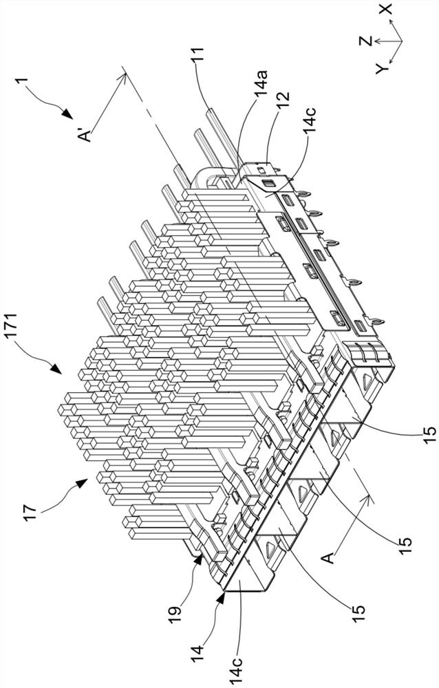
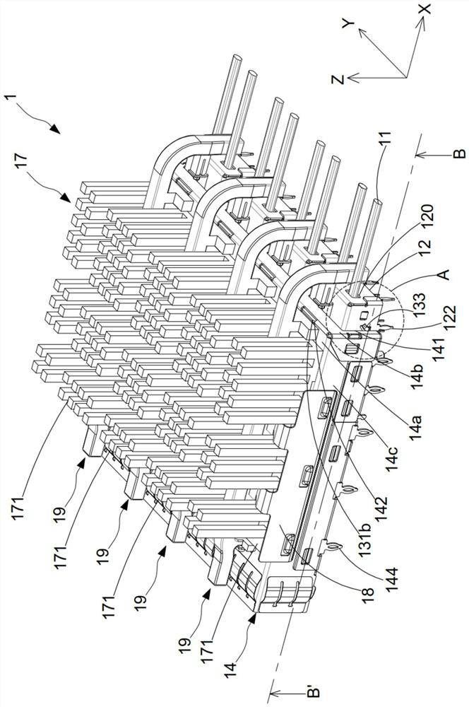
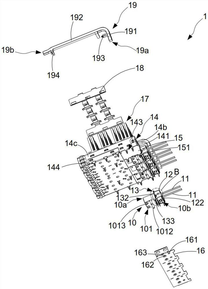
[0023] see figure 1 , figure 2 , image 3 , Figure 4 , Figure 5 and Figure 6 , is a perspective view, a partially exploded view, an assembly perspective view of the connector main body, a cable and a connection housing, of the electrical connector according to the first embodiment of the present application, figure 1 The sectional view along the line A-A' in and figure 2 The cross-sectional view along the line B-B'; as shown in the figure, the electrical connect...


PUM


Abstract

The invention discloses an electric connector which is connected with a chip connector and comprises a first terminal assembly, an adapter plate and a cable. The first terminal assembly comprises a plurality of terminals; the adapter plate is arranged on one side of the first terminal assembly, and at least one of a plurality of terminals of the first terminal assembly is connected with the adapter plate; one end of the cable is connected with the adapter plate, and the other end of the cable is connected with the chip connector. The plurality of terminals of the first terminal assembly are connected with the cable through the adapter plate, so that the selectivity of the size of the cable is increased, the welding process is simplified, the welding cost is reduced, and the connection stability between the terminals and the cable is improved.

Description

technical field [0001] The present application relates to the technical field of connectors, in particular to an electrical connector. Background technique [0002] At present, the requirements for the transmission rate of the connector are getting higher and higher. Generally, multiple terminals of the connector are usually plugged into the circuit board for external signal transmission, but the loss of the circuit board is becoming more and more obvious, so that the connector's The transfer rate cannot be increased. Therefore, cables are currently connected to multiple terminals of the connector, and signals are transmitted externally through the cables to reduce the impact of loss caused by the circuit board, so as to increase the transmission rate of the connector. However, the cable is directly welded to the terminal, and the size of the cable is easily limited by the size of the terminal, which increases the complexity of the welding process, thereby increasing the ov...

Claims


Application Information

Patent Timeline
Patent Type & Authority Applications(China)
IPC IPC(8): H01R31/06H01R4/02
CPCH01R31/06H01R4/029H01R12/721H01R12/53H01R13/6658H01R13/6471H01R12/585H01R13/405G02B6/3628H01R12/55H01R13/518
Inventor 黄斌郭荣哲陈琼南申欢欢陈宏基
Owner DONGGUAN LUXSHARE TECH CO LTD
Why Eureka
Try Eureka