Drilling traction robot support mechanism test device
What is AI technical title?
AI technical title is built by PatSnap AI team. It summarizes the technical point description of the patent document.
A supporting mechanism and testing device technology, which is applied in machine gear/transmission mechanism testing, machine/structural component testing, measuring devices, etc., can solve problems such as complex structure of experimental devices, reference of experimental data, and long experimental preparation period, etc., to achieve The effects of reduced experiment preparation period, reduced experiment cost, and simple structure of the experimental device
Active Publication Date: 2022-02-15
SOUTHWEST PETROLEUM UNIV
View PDF13 Cites 0 Cited by
Summary
Abstract
Description
Claims
Application Information
AI Technical Summary
This helps you quickly interpret patents by identifying the three key elements:
Problems solved by technology
Method used
Benefits of technology
Problems solved by technology
In terms of the drilling traction robot experimental system, two patents have been invented: CN201710705983.2 and CN201710720406.0, but these two patents can only carry out the traction force, traction speed and control experiments of the drilling traction robot, and cannot test the support of the supporting mechanism force, traction, and torque parameters, the reliability evaluation experiment of the support mechanism of the drilling traction robot cannot be carried out, and the anti-blocking characteristic experiment cannot be carried out
[0007] Therefore, because the existing downhole robot-related experimental devices are mainly complete machine experimental devices, the structure of the experimental device is extremely complicated, and the overall prototype of the drilling traction robot needs to be processed to carry out the experiment, resulting in a long test preparation period and high test costs, and it is impossible to provide a support mechanism. The structural optimization design provides experimental data reference, which to some extent restricts the theoretical research and engineering application of drilling traction robots
Method used
Image
Click on the blue label to locate the original text in one second.
Reading with bidirectional positioning of images and text.
Examples
Embodiment Construction
[0031] The present invention will be further described below in conjunction with accompanying drawing, protection scope of the present invention is not limited to the following:
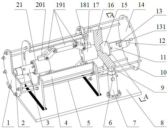
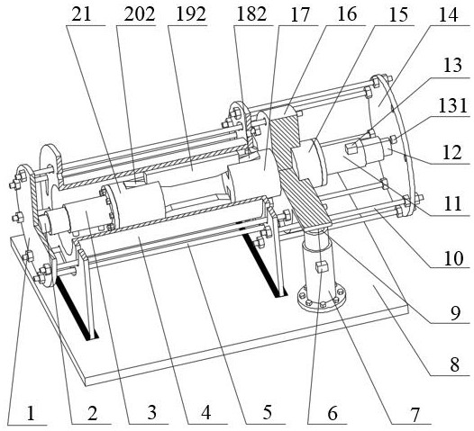
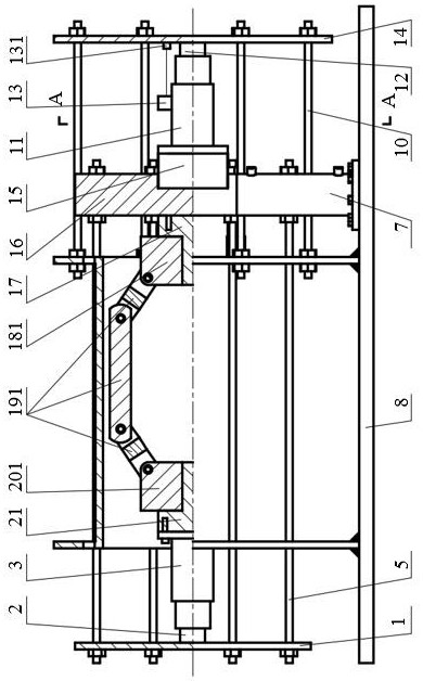
[0032] Such as Figure 1-8 Shown: the testing device for the support mechanism of the drilling traction robot, which includes a support baffle (1), tension and pressure sensor A (2), tension and pressure sensor B (12), tension and pressure sensor C (9), tension and pressure sensor D (23 ), hydraulic pressure A (3), hydraulic pressure B (11), hydraulic pressure C (7), hydraulic pressure D (22), displacement sensor A (13), displacement sensor B (6), simulated shaft (4), support rod (5 ), bottom plate (8), telescopic rod (10), telescopic baffle (14), axial thrust bearing (15), support / torque baffle (16), slider A (201 / 202), slider B ( 181 / 182), support block A (21), support block B (17), connecting rod support mechanism (191), wedge support mechanism (192). The left support plate (401) and the right sup...
PUM
Abstract
The invention relates to a testing device for a supporting mechanism of a drilling traction robot. It mainly consists of support baffle, tension and pressure sensor A, tension and pressure sensor B, tension and pressure sensor C, tension and pressure sensor D, hydraulic pressure A, hydraulic pressure B, hydraulic pressure C, hydraulic pressure D, displacement sensor A, displacement sensor B, simulated shaft, support It is composed of tie rod, bottom plate, telescopic pull rod, telescopic baffle, axial thrust bearing, support / torque baffle, slider A, slider B, support block A, support block B, connecting rod support mechanism, and wedge support mechanism. The purpose of the present invention is to provide a testing device for the support mechanism of a drilling traction robot, measure key parameters such as the support force, traction force, and torque of the support mechanism of the drilling traction robot, shorten the research and development cycle of the drilling traction robot, reduce the experimental cost of the drilling traction robot, and provide support for the optimal design of the support mechanism structure. The experimental data is used as a reference to promote the theoretical research and engineering popularization and application of drilling traction robots.
Description
technical field [0001] The invention relates to the field of downhole robots, in particular to a testing device for a supporting mechanism of a drilling traction robot. Background technique [0002] With the rapid development of my country's national economy and the improvement of people's living standards, my country's demand for energy has grown rapidly, and the contradiction between energy supply and demand has become increasingly prominent. The degree of dependence on foreign oil and natural gas has increased year by year. Climb to 45.3%, greatly exceeding the internationally recognized warning line, a serious threat to my country's energy security. With the deepening of exploration and development, low-permeability, low-porosity and other tight oil and gas (such as shale gas, etc.) have gradually become the focus of exploration and development. For example: According to the report of the United Nations Conference on Trade and Development in 2018, my country's shale gas ...
Claims
Application Information
Patent Timeline
Application Date:The date an application was filed.
Publication Date:The date a patent or application was officially published.
First Publication Date:The earliest publication date of a patent with the same application number.
Issue Date:Publication date of the patent grant document.
PCT Entry Date:The Entry date of PCT National Phase.
Estimated Expiry Date:The statutory expiry date of a patent right according to the Patent Law, and it is the longest term of protection that the patent right can achieve without the termination of the patent right due to other reasons(Term extension factor has been taken into account ).
Invalid Date:Actual expiry date is based on effective date or publication date of legal transaction data of invalid patent.

