

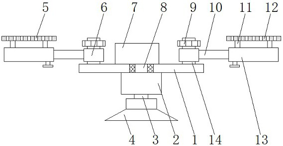
LED lamp capable of being quickly installed and convenient for angle adjustment
A technology for adjusting the angle and LED lights, which is applied to the parts of lighting devices, lighting devices, fixed lighting devices, etc., which can solve the problems of lack of quick installation, time-consuming and laborious installation, and small application scope of equipment, so as to achieve convenient connection and walking. Line, easy to use lighting, improve the effect of using stability
- Summary
- Abstract
- Description
- Claims
- Application Information
AI Technical Summary
Problems solved by technology
Method used
Image

Examples
Embodiment Construction
[0025] The following will clearly and completely describe the technical solutions in the embodiments of the present invention with reference to the accompanying drawings in the embodiments of the present invention. Obviously, the described embodiments are only some, not all, embodiments of the present invention. Based on the embodiments of the present invention, all other embodiments obtained by persons of ordinary skill in the art without making creative efforts belong to the protection scope of the present invention.
[0026] In the description of the invention, it should be noted that the terms "upper", "lower", "inner", "outer", "front end", "rear end", "both ends", "one end", "another end" etc. The indicated orientation or positional relationship is based on the orientation or positional relationship shown in the drawings, and is only for the convenience of describing the present invention and simplifying the description, rather than indicating or implying that the referre...
PUM
 Abstract
Description
Claims
Application Information