Abrasive circulating mechanism for sand blasting machine

A circulation mechanism and sandblasting machine technology, which is applied in the field of sandblasting machines, can solve the problems of sandblasting drop, reduced number of sandblasting, and consumption, etc., and achieve the effect of increasing the circulation speed

Inactive Publication Date: 2021-01-12
单县巨润新型材料有限公司
View PDF0 Cites 0 Cited by
  • Summary
  • Abstract
  • Description
  • Claims
  • Application Information

AI Technical Summary

Problems solved by technology

[0004] 1. During the sandblasting cycle of the sandblasting machine, the sandblasting adhered to the outer side of the cleaning wheel for cleaning the surface of the workpiece is easy to contact the workpiece again after rotation, which is easy to cause wear to the workpiece, and is easy to cause sticking Blasts attached to the cleaning wheel fall off, allowing fewer blasts to be recycled
[0005] 2. During the cycle of sandblasting, the sandblasting machine needs to use external equipment for sandblasting transportation between the sandblasting machine and the cyclone separator. The external equipment consumes more power resources during the working process

Method used


Image

  • Abrasive circulating mechanism for sand blasting machine
  • Abrasive circulating mechanism for sand blasting machine
  • Abrasive circulating mechanism for sand blasting machine

Examples


Embodiment Construction

[0026] In order to make the object, technical solution and advantages of the present invention clearer, the present invention will be further described in detail below in combination with specific embodiments and with reference to the accompanying drawings. It should be understood that these descriptions are exemplary only, and are not intended to limit the scope of the present invention. Also, in the following description, descriptions of well-known structures and techniques are omitted to avoid unnecessarily obscuring the concept of the present invention.

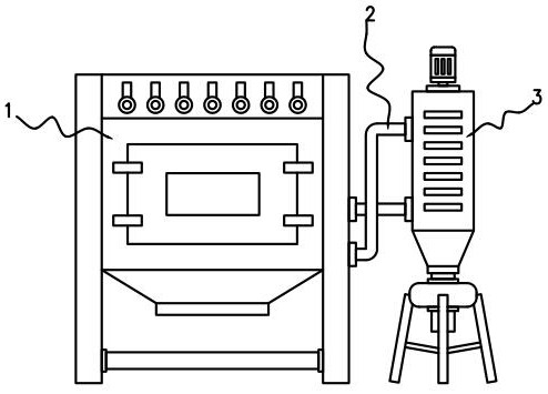
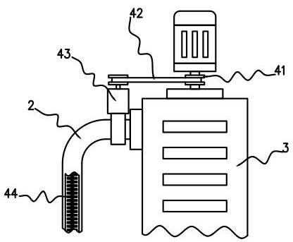
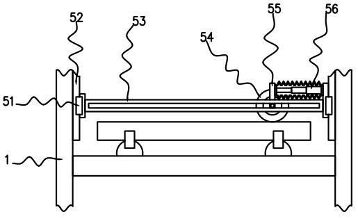
[0027] like Figure 1-4 As shown, an abrasive circulation mechanism for a sandblasting machine proposed by the present invention includes a sandblasting machine 1, one side of the outer wall of the sandblasting machine 1 is connected with a cyclone separator 3 through a transmission pipe 2, and both sides of the inner side wall of the sandblasting machine 1 A slide rail 52 is connected, the inner side wall of the slide r...


PUM


Abstract

The invention belongs to the field of sand blasting machines, and particularly relates to an abrasive circulating mechanism for a sand blasting machine. The abrasive circulating mechanism comprises the sand blasting machine, wherein one side of the outer side wall of the sand blasting machine is connected with a cyclone separator through a conveying pipe; the two sides of the inner side wall of the sand blasting machine are connected with sliding rails; the inner side walls of the sliding rails are connected with a sliding block; and one side of the outer side wall of the sliding block is connected with a supporting plate. Through the arrangement of a cleaning wheel, an electric push rod and a guide belt, blasting sand adhering to the cleaning wheel is scraped off when rotating to an aggregate plate so that a workpiece cannot be damaged when the blasting sand rotates to be in contact with the workpiece, the scraped blasting sand is transferred to the guide belt through the aggregate plate to fall in a centralized mode, and the number of the blasting sand is not reduced; and through the arrangement of a rotating wheel, a transmission belt and a shaftless auger, driving equipment ofthe cyclone separator can drive the shaftless auger in a connecting seat to rotate through the transmission belt, and thus the blasting sand conveyed in the conveying pipe can move more quickly without consuming too much power resource.

Description

technical field [0001] The invention relates to the field of sandblasting machines, in particular to an abrasive circulation mechanism for a sandblasting machine. Background technique [0002] Sand blasting machine uses compressed air to transport powdery granular materials from one place to another in the pipeline, and in the process of converting kinetic energy into potential energy, the high-speed moving sand particles scour the surface of the object to improve the surface quality of the object. . [0003] There are following problems in prior art: [0004] 1. During the sandblasting cycle of the sandblasting machine, the sandblasting adhered to the outer side of the cleaning wheel for cleaning the surface of the workpiece is easy to contact the workpiece again after rotation, which is easy to cause wear to the workpiece, and is easy to cause sticking The blasts attached to the cleaning wheel fall off, reducing the amount of blasts recycled. [0005] 2. During the cycl...

Claims


Application Information

Patent Timeline
Patent Type & Authority Applications(China)
IPC IPC(8): B24C3/04B24C9/00B24C7/00B08B1/02
CPCB08B1/02B24C3/04B24C7/0092B24C9/00B24C9/006
Inventor 刘珍华
Owner 单县巨润新型材料有限公司
Why Eureka
Try Eureka