Optical fiber coupling equipment capable of automatically adjusting stress of wire body according to rotating speed

An automatic adjustment, optical fiber coupling technology, applied in the field of optical fiber, can solve the problems of inconvenient use, difficult coupling of multiple line bodies, uneven line body stress, etc., and achieve the effect of convenient use

Inactive Publication Date: 2021-01-29
李冬梅
View PDF7 Cites 1 Cited by
  • Summary
  • Abstract
  • Description
  • Claims
  • Application Information

AI Technical Summary

Problems solved by technology

[0003] With the development of the optical fiber industry, it is often necessary to couple multiple optical fiber lines. In the current coupling process, the staff usually couple themselves, which is inconvenient to use, and the stress between the lines after coupling is not uniform. , which affects the use of optical fibers later, and it is also difficult to couple multiple wires. Therefore, in view of this, the existing structure and defects are studied and improved, and a method of automatically adjusting the stress of the wires according to the rotation speed is provided. Fiber-coupled equipment, in order to achieve a more practical purpose

Method used


Image

  • Optical fiber coupling equipment capable of automatically adjusting stress of wire body according to rotating speed
  • Optical fiber coupling equipment capable of automatically adjusting stress of wire body according to rotating speed
  • Optical fiber coupling equipment capable of automatically adjusting stress of wire body according to rotating speed

Examples


Embodiment Construction

[0020] The present invention will be further described below in conjunction with accompanying drawing:

[0021] as attached figure 1 to attach Figure 5 Shown:

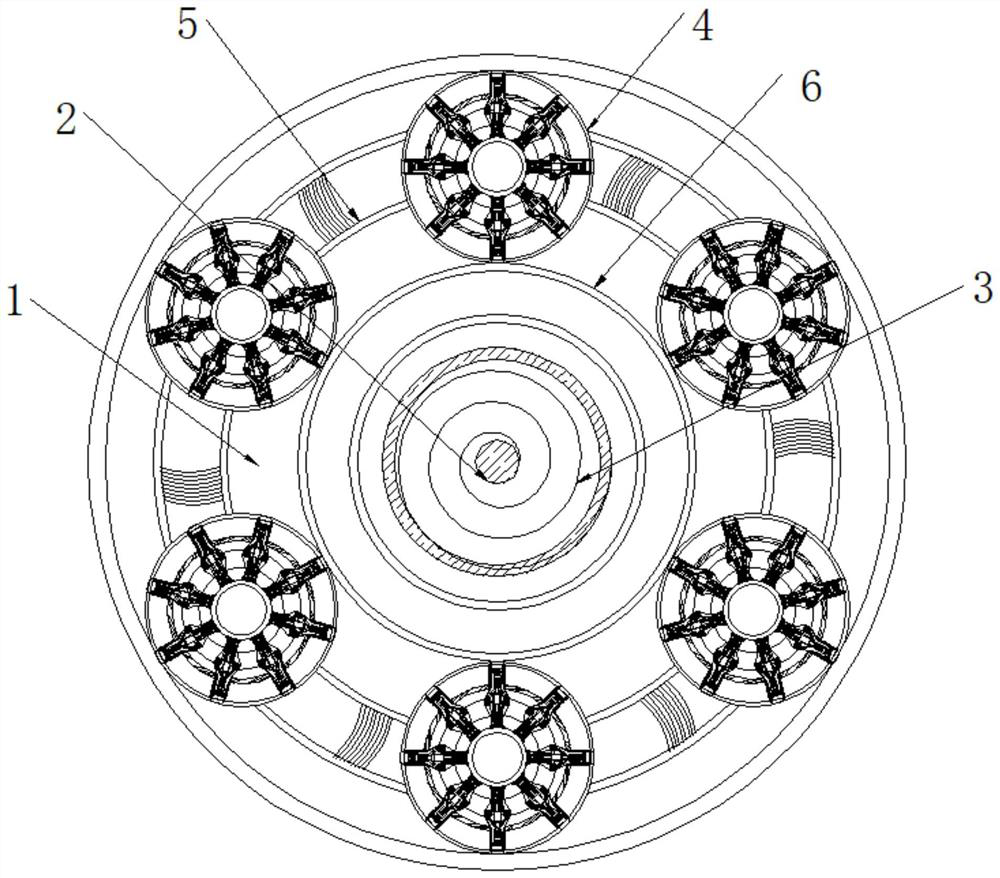
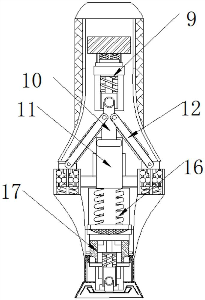
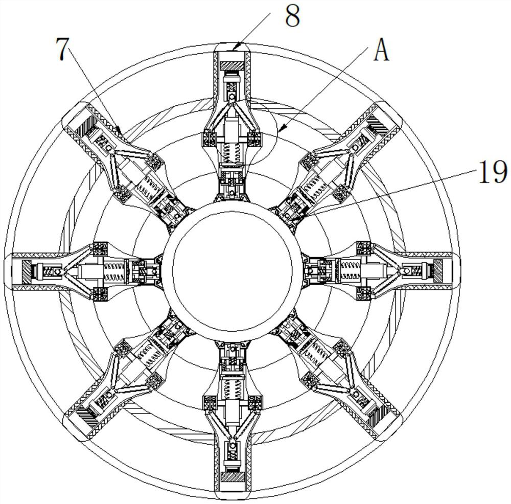
[0022] The present invention provides an optical fiber coupling device that automatically adjusts the stress of the line body according to the rotating speed, which includes a production seat 1, the interior of the production seat 1 is connected with a rotating shaft 2, and the outer surface of the rotating shaft 2 is movably connected with a coil spring 3, and the production seat 1 The inside of 1 is fixedly connected with coupling seat 4, the diameter of coil spring 3 is larger than the diameter of rotating shaft 2, the diameter of rotating disk 6 is larger than the diameter of rotating shaft 2, the side surface of coupling seat 4 is fixedly connected with supporting seat 5, and the production seat 1 The inside of the coupling seat 4 is movably connected with a rotating disc 6, the inside of the coupling seat 4 is...


PUM


Abstract

The invention belongs to the technical field of optical fibers, and particularly relates to optical fiber coupling equipment capable of automatically adjusting the stress of a wire body according to the rotating speed, wherein the optical fiber coupling equipment comprises a production seat, a rotating shaft is rotatably connected to the interior of the production seat, a coil spring is movably connected to the outer surface of the rotating shaft, and a coupling seat is fixedly connected to the interior of the production seat. A supporting seat is fixedly connected to the side surface of the coupling seat, a rotating disc is movably connected to the interior of the production seat, a protective seat is fixedly connected to the interior of the coupling seat, an electromagnetic seat is fixedly connected to the interior of the protective seat, and a magnetic seat is movably connected to the side, away from the electromagnetic seat, of the interior of the protective seat; a compression rodis movably connected to the side surface of the magnetic seat, and one end of the compression rod penetrates through the interior of a hollow cavity base. During use, the effect of keeping the rotating speed to properly wind an optical fiber body can be achieved, the internal stress is uniform after coupling is completed, and beneficial effects are brought to later use of the optical fiber.

Description

technical field [0001] The invention belongs to the field of optical fiber technology, in particular to an optical fiber coupling device that automatically adjusts the stress of a line body according to the rotating speed. Background technique [0002] Optical fiber communication systems can use single-mode or multi-mode optical fibers. Fiber optic connectors connect the cores of these fibers together so that light can travel from one fiber to another. Typically, a fiber optic plug includes a protruding barrel A ferrule in which an optical fiber is mounted axially within the cylindrical ferrule, the optical fiber terminating at the end of the ferrule and terminated with a similar ferrule / fiber optic assembly within the connector. [0003] With the development of the optical fiber industry, it is often necessary to couple multiple optical fiber lines. In the current coupling process, the staff generally do the coupling by themselves, which is inconvenient to use, and the stre...

Claims


Application Information

Patent Timeline
Patent Type & Authority Applications(China)
IPC IPC(8): G02B6/38
CPCG02B6/3898
Inventor 李冬梅
Owner 李冬梅
Why Eureka
Try Eureka