Visual measurement device for crack repair and using method

A measuring device and crack technology, applied in the field of rock crack repair, can solve problems such as difficult cracks, simulation, and many rocks and soils, and achieve the effect of increasing the degree of lubrication

Active Publication Date: 2021-04-09
合肥九州龙腾科技成果转化有限公司
View PDF5 Cites 2 Cited by
  • Summary
  • Abstract
  • Description
  • Claims
  • Application Information

AI Technical Summary

Problems solved by technology

[0002] Due to the complexity of geotechnical engineering, the influence of environmental factors, regional factors and external factors, there are many uncertain factors in the rock and soil itself. The complex geological conditions make it difficult to simulate the cracks in the rock and soil in the laboratory. However, it is difficult to completely repair small cracks with the commonly used mortar repair.

Method used


Image

  • Visual measurement device for crack repair and using method
  • Visual measurement device for crack repair and using method
  • Visual measurement device for crack repair and using method

Examples


Embodiment 1

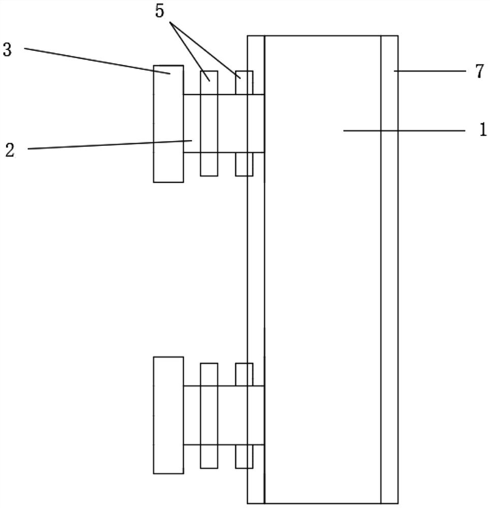
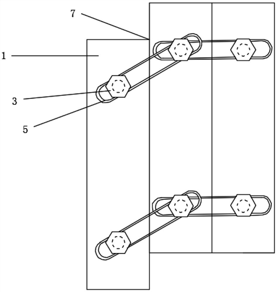
[0039] Such as Figure 1-6 As shown, a visual measurement device for crack repair, which includes a turn frame structure assembled around a plurality of steel plates 1, each bottom corner of the turn frame structure is welded and fixed for the entire turn frame structure The threaded plate 4 for support; the contact end surfaces of two adjacent steel plates 1 are connected by a mortise and tenon sliding structure; the outer walls of two adjacent steel plates 1 are connected by a sliding lever structure, and make the adjacent two The plates 1 can slide up and down within a certain range. By adopting the measuring device with the above structure, the crack is surrounded by the flip template structure, and the shape of the crack and the geological environment are rubbed through the rubbing effect of silica gel. However, considering that the surface crack is too small, the silica gel cannot flow into the crack, so the silica gel Add nano-scale magnetic powder into the mixture, us...

Embodiment 2

[0043] The method for using the visual measurement device for crack repair comprises the following steps:

[0044] The first step: Prepare materials: steel plate 1, screw rod 2, nut 3, bolt plate 4, sliding lever 5, super glue, stainless steel sliding bar 7, silica gel, silicone oil, nano-scale magnetic powder, transparent resin, iron frame, lighting, magnets and jacks;

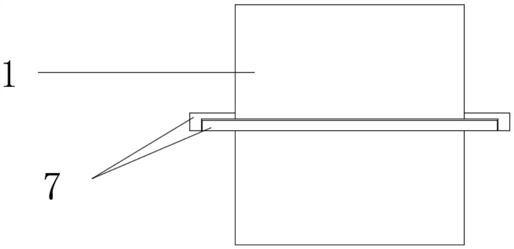
[0045]Step 2: Install the formwork frame structure: Weld the screw rod 2 at the same position up and down on one side of each steel plate 1, weld the stainless steel sliding strip 7 on both sides of the steel plate 1, the left side is the tenon wrapping structure, and the right side is the tenon Eyelet structure, two adjacent steel plates 1 form a sliding fit through tenons and mortises, and the corners of the rectangular frame structure are fixed together by welding, and the bottom of the steel plate at the bottom edge of the four corners of the formwork structure is welded for The whole device is supported...


PUM


Abstract

The invention discloses a visual measuring device for crack repair and a using method. The visual measurement device comprises a mold-making rack structure formed by by assembling a plurality of steel plates in a surrounding mode, and a threaded plate used for supporting the whole mold-making rack structure is welded and fixed to each bottom corner of the mold-making rack structure; the contact end faces of every two adjacent steel plates are connected through a mortise and tenon sliding structure; and the outer side walls of every two adjacent steel plates are connected through a sliding lever structure, and every two adjacent steel plates can slide up and down within a certain range. According to the device, when cracks difficult to observe are repaired, a transparent sample is molded twice by utilizing the rubbing function of the silica gel and the transparent resin; and different repairing mortar is selected to repair rubbed cracks, the critical crack filling depth and the critical crack filling width of the mortar are observed, and the device can be used for observing and repairing.

Description

technical field [0001] The invention relates to the technical field of rock crack repair, in particular to a visual measurement device for crack repair and a method for using it. Background technique [0002] Due to the complexity of geotechnical engineering, the influence of environmental factors, regional factors and external factors, there are many uncertain factors in the rock and soil itself. The complex geological conditions make it difficult to simulate the cracks in the rock and soil in the laboratory. However, it is difficult to completely repair small cracks with the commonly used mortar repair. Contents of the invention [0003] The purpose of the present invention is to provide a visual measurement device for crack repair and its use method. When repairing cracks that are difficult to observe, the device uses the rubbing function of silica gel, and then uses transparent resin to mold a transparent sample for the second time. Then choose different repair mortar...

Claims


Application Information

Patent Timeline
Patent Type & Authority Applications(China)
IPC IPC(8): E02D3/00
CPCE02D3/00
Inventor 刘杰孙荣琪宋瑞汪岩松陈子悦郭建祥李运舟杜卓兴杨浩宇石谦李洪亚唐洪宇谢晓康孙涛黎照李政
Owner 合肥九州龙腾科技成果转化有限公司
Why Eureka
Try Eureka