Double-turbulent-flow combined oil flinger

An oil throwing tray and combined technology, applied in combustion methods, combustion chambers, combustion equipment, etc., can solve problems such as insufficient oil throwing volume, poor atomization effect, small fuel atomization cone angle, etc. Good temperature field distribution, good atomization effect, and improved combustion efficiency

Inactive Publication Date: 2021-06-25
NORTHWESTERN POLYTECHNICAL UNIV
View PDF0 Cites 3 Cited by
  • Summary
  • Abstract
  • Description
  • Claims
  • Application Information

AI Technical Summary

Problems solved by technology

[0004] However, the disadvantages of the existing oil thrower nozzles are that the fuel atomization cone angle is not large at low speeds, the amount of oil thrown by each nozzle is not uniform enough, and the atomization effect needs to be improved.

Method used


Image

  • Double-turbulent-flow combined oil flinger
  • Double-turbulent-flow combined oil flinger

Examples


Embodiment Construction

[0020] The present invention will be further described now in conjunction with accompanying drawing:

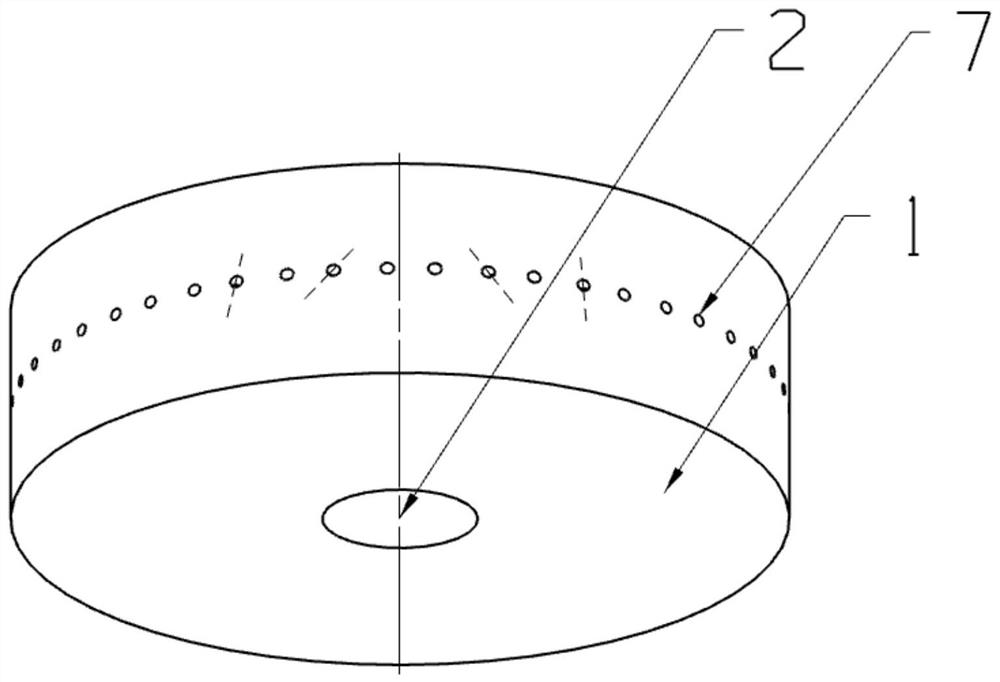
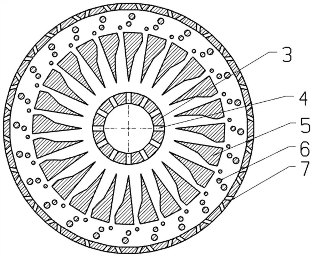
[0021] combine figure 1 , figure 2 , the present invention is a double turbulence combined oil flinger.

[0022] When it works, the liquid fuel flows into the cavity of the oil thrower through the oil inlet 2, and enters the interior of the oil thrower through the diverter 3, so that the fuel injection amount reaches each oil hole through the splitter channel 4 to be equal, and then flows through the special-shaped spoiler vanes in turn 5 and bubble-type spoiler 6, due to the high-speed rotation of the disc main body 1, the fuel is thrown at the spoiler blade and the spoiler area, and after being torn, crossed, and changed, the atomization effect of the liquid flow is better, The larger the expansion cone angle, the more fully mixed with the air in the combustion chamber. And the hedge nozzle 7 makes the tissue burn more fully, and the outlet temperature field is more eve...


PUM


Abstract

The invention provides a double-turbulent-flow combined oil flinger. The double-turbulent-flow combined oil flinger is composed of a flinger body, a flow divider, special-shaped turbulent-flow blades, bubble distribution turbulent-flow columns and opposite punching holes. The flow divider is of a cover cap structure with a lateral opening and is installed on an oil inlet. The special-shaped turbulent-flow blades are evenly distributed at the outlet of the flow divider in the circumferential direction, and channels between the blades limit the flow direction of working media. The bubble turbulent-flow columns are different in size and are distributed at the rear ends of the turbulent-flow blades. And the opposite punching holes are alternately distributed in the central wall surface of the oil flinger. Fuel oil enters the flow divider from an oil inlet, then is forked and turned at the position of the turbulent-flow blades, and collides for multiple times in the area of the turbulent-flow columns to break a liquid film, and finally, a better atomization effect is achieved at a opposite punching nozzle. And moreover, the fuel oil has a cooling effect on a high-speed rotating shaft and can also be preheated, so that the combustion efficiency of an engine using the oil flinger is relatively high.

Description

technical field [0001] The invention relates to the technical field of combustion chambers of gas turbines, in particular to a double turbulence combined oil flinger. Background technique [0002] The oil thrower of the turbine engine is a structure that works on the fuel through the rotation of the oil thrower, so that the fuel is sprayed out at high speed through the nozzle holes of the oil thrower to achieve fuel atomization. The rotational speed of the oil slinger is consistent with the rotational speed of the turbine shaft and is constantly changing with the flight status. [0003] The oil flinger is a special form of fuel nozzle, which is mainly used for the oil supply device of the baffle annular combustion chamber with high speed and small flow. The fuel is supplied through the center of the hollow compressor-turbine shaft, and there are several small holes on the periphery of the oil throwing pan. When the central shaft of the engine rotates at high speed, the fuel...

Claims


Application Information

Patent Timeline
Patent Type & Authority Applications(China)
IPC IPC(8): F23R3/38
CPCF23R3/38
Inventor 张群马晓曦王晓燕高耀红王紫欣
Owner NORTHWESTERN POLYTECHNICAL UNIV
Why Eureka
Try Eureka