Jet type fuse insulation operating rod

The technology of jet fuse and insulating operating rod is applied in the field of jet fuse insulating operating rod and insulating pull rod, which can solve the problems of affecting the reliability of power supply, prolonging the power outage time of users, inconvenient for manual disassembly and assembly of jet fuse, etc. Achieve the effect of enhancing the scope of use, improving installation efficiency, and facilitating installation

Pending Publication Date: 2021-07-02
JINGHAI ELECTRIC POWER SUPPLY COMPANY OF STATE GRID TIANJIN ELECTRIC POWER +1
View PDF1 Cites 0 Cited by
  • Summary
  • Abstract
  • Description
  • Claims
  • Application Information

AI Technical Summary

Problems solved by technology

[0003] Since the fuse of the fuse is tubular, the line needs to be cut off during installation. The operator climbs on the pole and inserts the fuse tube upward from the bottom of the porcelain sleeve of the fuse for installation, which not only prolongs the power outage time of the user, but also affects the power supply. reliability
[0004] The publication number is CN210897179U, which discloses a patent name of a 10KV insulating pull rod suitable for jet fuses. Although it solves the problem of manual disassembly and assembly of jet fuses, due to the variety of specifications of jet fuses, it is difficult to use them now. Some insulating rods of one specification cannot make the disassembly and assembly of fuses easier. Therefore, it is necessary to design a versatile insulating rod that can be used for multi-standard fuses.

Method used


Image

  • Jet type fuse insulation operating rod
  • Jet type fuse insulation operating rod
  • Jet type fuse insulation operating rod

Examples


Embodiment Construction

[0030] Embodiments of the present invention are described in further detail below in conjunction with the accompanying drawings:

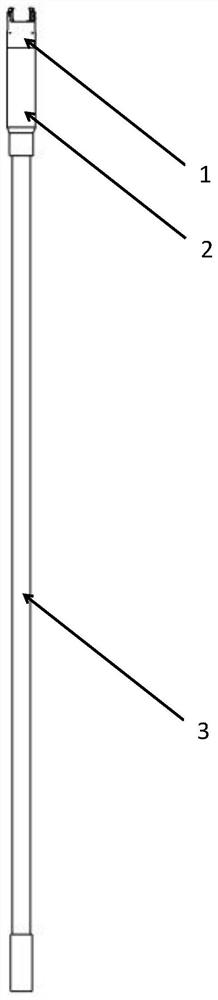
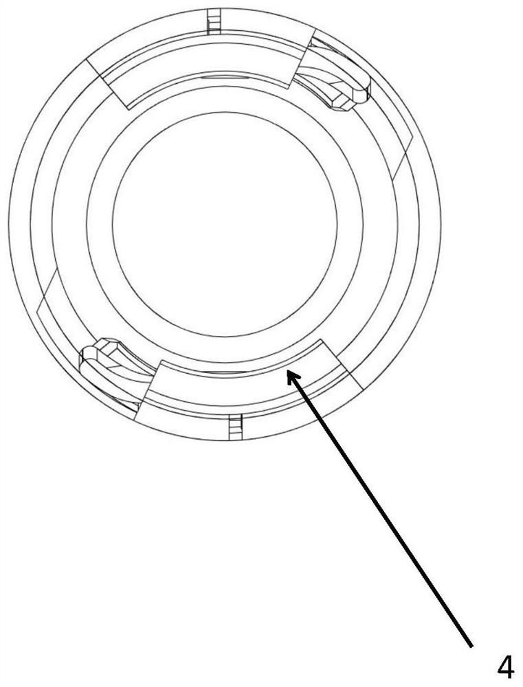
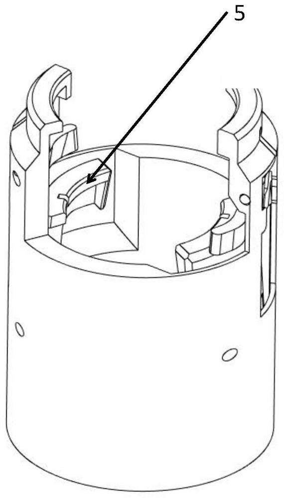
[0031] An insulated operating rod for a spray type fuse, which includes an insulating pull rod 3, and its innovation is that it also includes an extension tube 2 and a clip joint 1. An extension tube is threaded on the upper part of the insulation pull rod, and the upper end of the extension tube is The snap joint is installed on the thread; the snap joint is mainly composed of a cylinder body 10, a snap arc plate 4, a holding tooth 15 and a claw 5, and there are spaced and oppositely arranged gaps on the upper end surface of the cylinder body. The arc plates are clamped, and there are installation openings 9 on the cylinder wall directly below the two clamping arc plates, and holding teeth are installed in each installation opening through the first torsion spring, and the inner wall of the cylinder below each holding tooth Both of them are equipp...


PUM


Abstract

The invention relates to an insulated operating rod of a jet fuse, and the operating rod comprises an insulated pull rod and is characterized by further comprising an extension tube and a clamping joint; the extension tube is mounted at the upper part of the insulated pull rod in a threaded manner, and the clamping joint is mounted at the upper end of the extension tube in a threaded manner; the clamping connector is mainly composed of a barrel, clamping arc plates, holding teeth and clamping jaws, the clamping arc plates which are oppositely arranged at intervals are arranged on the upper end face of the barrel, mounting openings are formed in the barrel wall, under the two clamping arc plates, of the barrel, the holding teeth are mounted in the mounting openings through first torsion springs, and the clamping jaws are connected with the clamping arc plates. clamping jaws are mounted on the inner wall of the cylinder body below the holding teeth through second torsion springs; and the torsion of the first torsion springs is greater than that of the second torsion springs. The injection type fuse insulating pull rod is scientific and reasonable in design, has the advantages of being high in universality, convenient to install, capable of improving installation efficiency and easy to achieve, and has high innovativeness.

Description

technical field [0001] The invention belongs to the field of electric construction tools, and relates to an insulating pull rod, in particular to an insulating operating rod for a spray type fuse. Background technique [0002] With the continuous development of the "coal-to-electricity" project, a large number of new equipment have been put into production one after another, and a number of column-mounted integrated transformers with new structures have emerged, that is, jet fuses. It is mainly used in urban and rural power transmission and distribution systems in the power industry, and can realize full-scale protection (overload and open circuit faults). It is an updated product of the traditional drop-out high-voltage fuse. The injection fuse is composed of a porcelain bushing and a fuse tube inserted in it. The lower contact of the porcelain bushing is a bell-shaped structure, which has the function of straightening and guiding the fuse tube, so that the success rate of ...

Claims


Application Information

Patent Timeline
Patent Type & Authority Applications(China)
IPC IPC(8): H01H85/02H01H85/05H01H85/20
CPCH01H85/02H01H85/05H01H85/20
Inventor 解红永刘旭石振磊舒艳王雅君宋建刚刘玉魁李拥军徐福华刘仲超
Owner JINGHAI ELECTRIC POWER SUPPLY COMPANY OF STATE GRID TIANJIN ELECTRIC POWER
Why Eureka
Try Eureka